Asus Vintage-AH1 User Manual
Page 70
4 - 1 1
4 - 1 1
4 - 1 1
4 - 1 1
4 - 1 1
A S U S V i n t a g e - A H 1
A S U S V i n t a g e - A H 1
A S U S V i n t a g e - A H 1
A S U S V i n t a g e - A H 1
A S U S V i n t a g e - A H 1
Never connect a U S B c a b l e
U S B c a b l e
U S B c a b l e
U S B c a b l e
U S B c a b l e to the IEEE 1394b connectors. Doing so
will damage the motherboard!
1 2 .
1 2 .
1 2 .
1 2 .
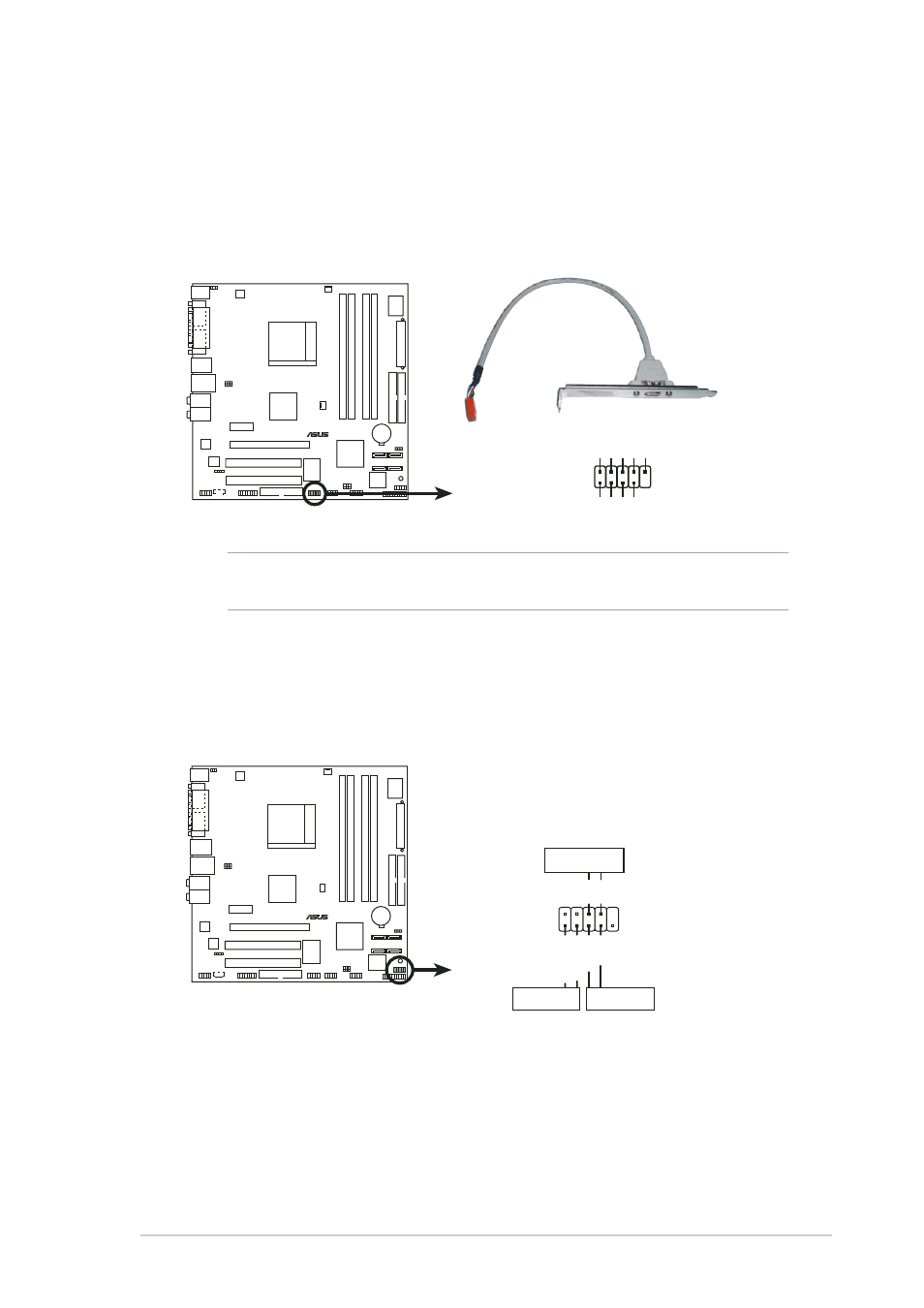
1 2 . I E E E 1 3 9 4 c o n n e c t o r s
I E E E 1 3 9 4 c o n n e c t o r s
I E E E 1 3 9 4 c o n n e c t o r s
I E E E 1 3 9 4 c o n n e c t o r s
I E E E 1 3 9 4 c o n n e c t o r s
( 1 0 - 1 p i n I E 1 3 9 4 B _ 1 , I E 1 3 9 4 B _ 2 [ P u r p l e ] )
( 1 0 - 1 p i n I E 1 3 9 4 B _ 1 , I E 1 3 9 4 B _ 2 [ P u r p l e ] )
( 1 0 - 1 p i n I E 1 3 9 4 B _ 1 , I E 1 3 9 4 B _ 2 [ P u r p l e ] )
( 1 0 - 1 p i n I E 1 3 9 4 B _ 1 , I E 1 3 9 4 B _ 2 [ P u r p l e ] )
( 1 0 - 1 p i n I E 1 3 9 4 B _ 1 , I E 1 3 9 4 B _ 2 [ P u r p l e ] )
These connectors are for IEEE 1394b ports. Connect the IEEE 1394
module cable to this connector, then install the module to a slot
opening at the back of the system chassis.
1 3 .
1 3 .
1 3 .
1 3 .
1 3 . System front panel connector (10-1 pin F_PANEL1)
S y s t e m f r o n t p a n e l c o n n e c t o r ( 1 0 - 1 p i n F _ P A N E L 1 )
S y s t e m f r o n t p a n e l c o n n e c t o r ( 1 0 - 1 p i n F _ P A N E L 1 )
S y s t e m f r o n t p a n e l c o n n e c t o r ( 1 0 - 1 p i n F _ P A N E L 1 )
S y s t e m f r o n t p a n e l c o n n e c t o r ( 1 0 - 1 p i n F _ P A N E L 1 )
This connector supports several front panel chassis-mounted
functions.
•
H a r d d i s k d r i v e a c t i v i t y L E D ( R e d 2 - p i n I D E L E D )
H a r d d i s k d r i v e a c t i v i t y L E D ( R e d 2 - p i n I D E L E D )
H a r d d i s k d r i v e a c t i v i t y L E D ( R e d 2 - p i n I D E L E D )
H a r d d i s k d r i v e a c t i v i t y L E D ( R e d 2 - p i n I D E L E D )
H a r d d i s k d r i v e a c t i v i t y L E D ( R e d 2 - p i n I D E L E D )
This 2-pin connector is for the HDD Activity LED. Connect the HDD
Activity LED cable to this connector. The IDE LED lights up or flashes
when data is read from or written to the HDD.
®
IEEE 1394 connector
IE1394_1
1
TP
A1-
GND
TPB1-
+12V
GND
TP
A1+
GND
TPB1+
+12V
®
System panel connector
F_PANEL1
PWR
Ground
GND
Reset
IDE_LED+
IDE_LED-
RESET
IDE LED
PWRSW