Pc-dl intel panel connector fp_audio1, Pc-dl system panel connector – Asus AP1720-E1 User Manual
Page 58
2-32
Chapter 2: Hardware information
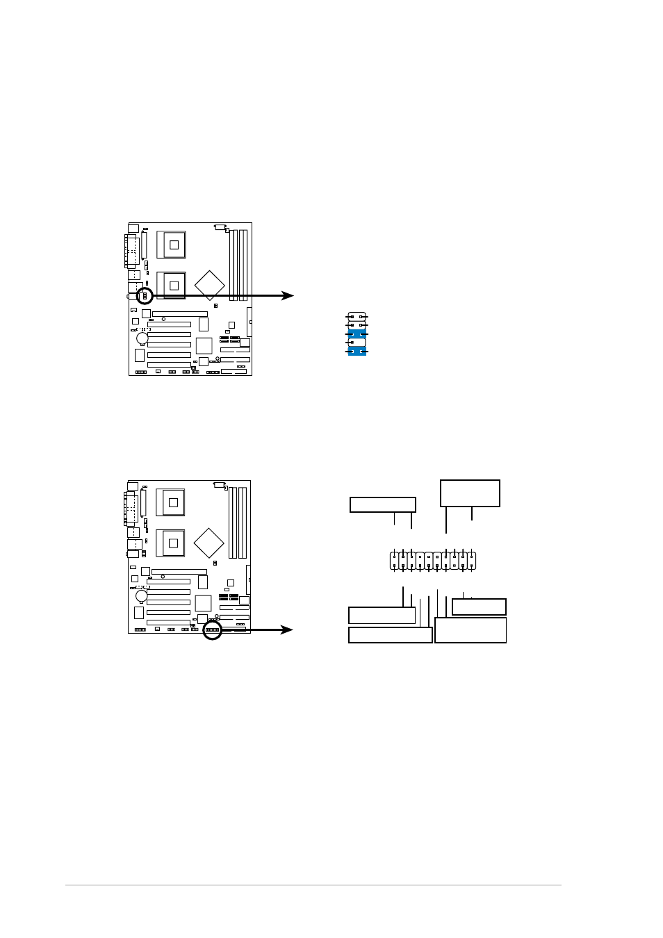
15. Front panel audio connector (10-1 pin FP_AUDIO1)
This is an interface for the Intel front panel audio cable that allow
convenient connection and control of audio devices.
By default, the pins labeled LINE OUT_R/BLINE_OUT_R and the pins
LINE OUT_L/BLINE_OUT_L are shorted with jumper caps. Remove
the caps only when you are connecting the front panel audio cable.
16. System panel connector (20-pin PANEL1)
This connector accommodates several system front panel functions.
•
System Power LED Lead (3-1 pin PLED)
This 3-1 pin connector connects to the system power LED. The LED
lights up when you turn on the system power, and blinks when the
system is in sleep mode.
•
Hard Disk Activity Lead (2-pin IDELED)
This 2-pin connector is for the HDD LED cable. The read or write
activities of the device connected to the any of IDE connectors cause
the IDE LED to light up.
PC-DL
PC-DL Intel Panel Connector
FP_AUDIO1
BLINE_OUT_L
MIC2
Line out_R
Line out_L
BLINE_OUT_R
NC
MICPWR
+5VA
AGND
PC-DL
PC-DL System Panel Connector
*
Requires an ATX power supply.
PLED
Ground
MLED
PWR
+5VSB
+5V
Speaker
Power LED
Ground
+5V
Reset SW
SMI Lead
Message LED
ExtSMI#
Ground
Reset
HD_LED+
HD_LED-
ATX Power
Switch*
LAN_LINK
LAN_ACT
Speaker
Connector