Installieren der cpu, Motherboard layout, Deutsch – Asus K8N User Manual
Page 5: Asus k8n-motherboard, Pci1, Pci2 pci3 pci4 pci5
5
Deutsch
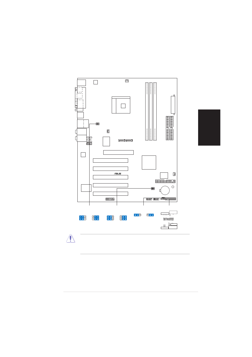
ASUS K8N-Motherboard
2.
Installieren der CPU
Folgen Sie bitte den nachstehenden Schritten, um eine CPU zu installieren.
1. Suchen Sie auf dem Motherboard den 754-pol. ZIF-Sockel.
2. Heben Sie den Sockelhebel bis zu einem Winkel von 90 Grad hoch.
1.
Motherboard layout
Stecken Sie unbedingt das Netzkabel aus, bevor Sie DIMMs oder
andere Systemkomponenten installieren oder entfernen. Anderfalls
können das Motherboard und andere Systemkomponenten schwer
beschädigt werden
.
PCI1
PANEL
K8N
CR2032 3V
Lithium Cell
CMOS Power
CD
AUX
Super
I/O
4Mbit
BIOS
Accelerated Graphics Port (AGP)
FP_AUDIO
Audio
Codec
USB2.0
T: USB3
B: USB4
Top:
RJ-45
GAME
ATX12V
CHASSIS
PRI_IDE
SEC_IDE
A
TX Power Connector
USB1
USB2
nVIDIA
nForce3
250
10/100
LAN
PHY
USB78
SB_PWR
CHA_FAN
USBPW12
USBPW34
PS/2KBMS
T: Mouse
B: Keyboard
DDR DIMM1 (64 bit,184-pin module)
DDR DIMM2 (64 bit,184-pin module)
DDR DIMM3 (64 bit,184-pin module)
PCI2
PCI3
PCI4
PCI5
SATA1
USB56
SATA2
CPU_FAN
PWR_FAN
Socket 754
CLRTC
Below:Mic In
Center:Line Out
Top:Line In
FLOPPY
Bottom:
Center/Subwoofer
Middle:
Side surround L/R
Top:
Rear Surround L/R
P
ARALLEL
PORT
COM1
SPDIF_O1
SPDIF_O2
USBPW56
USBPW78
* Requires an ATX power supply.
PLED-
PWR
+5V
Speaker
Speaker
Connector
Power LED
Ground
Reset SW
IDE_LED
IDE_LED+
Ground
Reset
Ground
Ground
ATX Power
Switch*
PLED+
IDE_LED-
PANEL
3
2
2
1
+5V
(Default)
+5VSB
USBPW56
USBPW78
3
2
2
1
+5V
(Default)
+5VSB
USBPW12
USBPW34
2
1
3
2
CLRTC
Normal
Clear CMOS
(Default)