8 chapter 4: motherboard info, Atx power connector cd (black) – Asus P1-P5945G User Manual
Page 53
4-8
Chapter 4: Motherboard info
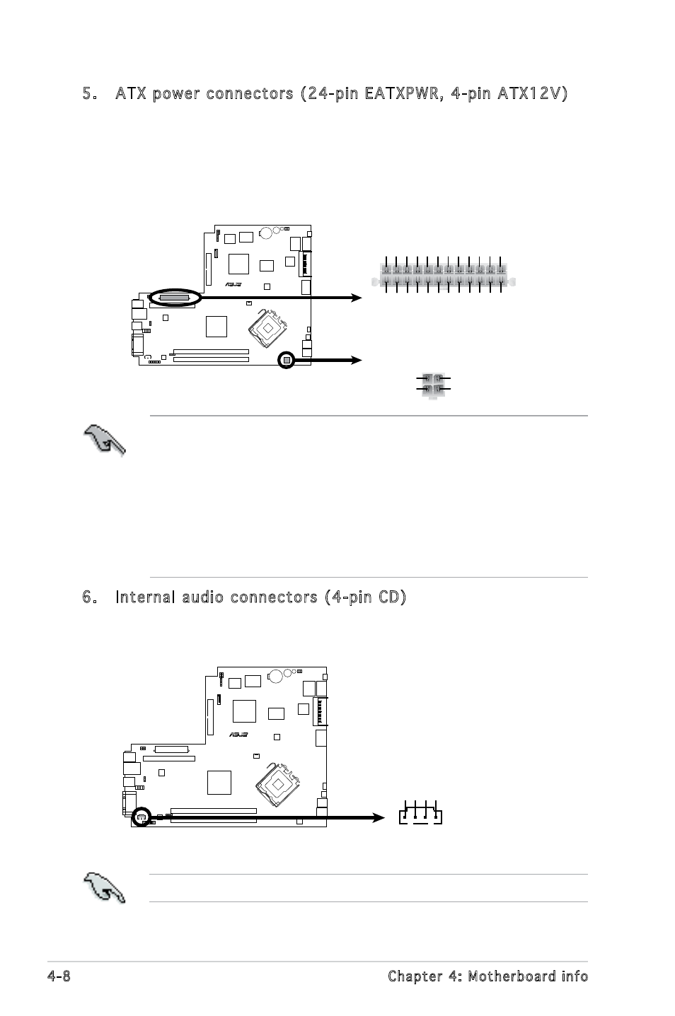
5. ATX power connectors (24-pin EATXPWR, 4-pin ATX12V)
These connectors are for ATX power supply plugs. The plugs from
the power supply are designed to fit these connectors in only one
orientation. Find the proper orientation and push down firmly until the
connectors completely fit.
R
ATX Power Connector
+12V DC
GND
+12V DC
GND
ATX12V
+3
Vo
lts
+3
Vo
lts
Ground +5
Vo
lts
+5
Vo
lts
Ground
Ground Power OK +5V Standby +12
Vo
lts
-5 V
olts
+5
Vo
lts
+3
Vo
lts
-12
Vo
lts
Ground
Ground
Ground
PSON#
Ground
+5
Vo
lts
+12
Vo
lts
+3
Vo
lts
+5
Vo
lts
Ground
EATXPWR
• Do not forget to connect the 4-pin ATX +12 V power plug;
otherwise, the system will not boot.
• Use of a PSU with a higher power output is recommended when
configuring a system with more power-consuming devices. The
system may become unstable or may not boot up if the power is
inadequate.
• Make sure that your power supply unit (PSU) can provide at least
the minimum power required by your system.
6. Internal audio connectors (4-pin CD)
These connectors allow you to receive stereo audio input from sound
sources such as a CD-ROM, TV tuner, or MPEG card.
Enable the CD-IN function in the audio utility when using this connector.
R
ATX Power Connector
CD
(black)
Right
Audio Channel
Left
Audio Channel
Ground
Ground