10 chapter 4: motherboard info, Front panel audio connector, Aafp – Asus V3-M2NC61P User Manual
Page 66: Speaker out connector speaker
4-10
Chapter 4: Motherboard info
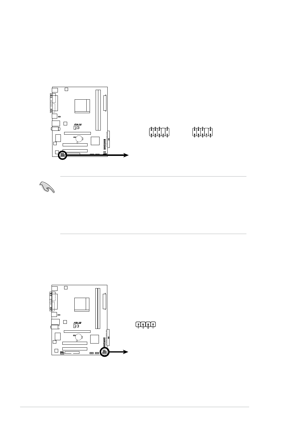
8. Front panel audio connector (10-1 pin AAFP)
This connector is for a chassis-mounted front panel audio I/O module that
supports either High Definition Audio or AC`97 audio standard. Connect one
end of the front panel audio I/O module cable to this connector.
• We recommend that you connect a high-definition front panel audio
module to this connector to avail of the motherboard high-definition audio
capability.
• By default, this connector is set to HD Audio. If you want to connect
a High Definition front panel audio module to this connector, set the Front
Panel Select item in the BIOS to [HD Audio]. See section “5.4.2 Chipset”
for details.
R
Front Panel Audio Connector
HP_HD
MIC2_L
HP_R
HP
_L
MIC2_J
D
Jack_Sens
e
MIC2_R
PRESENSE#
AGND
AAFP
Legacy AC’97-compliant
pin definition
NC
MIC2_L
Line out_R
Line out_L
NC
NC
MIC2_R
NC
AGND
Azalia-compliant
pin definition
9. Speaker connector (4-pin SPEAKER)
This connector is for the chassis-mounted system warning speaker. The
speaker allows you to hear system beeps and warnings.
R
Speaker Out Connector
SPEAKER
+5
V
GN
D
GN
D
Speaker Ou
t
1