Comfort Stat CP1719 User Manual
Page 2
Mechanical Heat Backup
This thermostat includes a bimetal switch that will automatically turn on the Heat when
the temperature reaches about 41˚F (5˚C).
WARNING: This switch only activates the Heating terminal (W). The system itself
must be capable of automatically turning the Fan On. Without normal Fan
operation, severe damage to the heating system could result.
Selector Switches
In order for this thermostat to control your system, the system type must be specified
by the selector switches on the printed circuit board inside the thermostat. There is
also a selector switch for your choice of Fahrenheit or Celsius temperature display.
y F˚ / C˚ selector (Fahrenheit / Celsius)
Your thermostat is set for F˚ mode from the factory. In order to change to C˚ mode,
slide the switch to C˚ and Move the battery out and wait for about 1 minute then place
the batteries ..
NOTE: Unless press any key about 2 seconds without the battery, then place the
battery again. the thermostat will not change temperature mode. All programs and
ce or an oil burner. If you have an electric furnace, test to see whether
ating, change the switch position to “HE”. The system selector
or emergency heat source), then slide the switch
STALLA
settings will be lost .
y Heating System Selector (HG – HE switch)
The factory position for this switch is in the “HG” position. Leave in this position if you
have a gas furna
the Heat and Fan come on as expected after installation. If the Fan operation is normal,
leave it in the “HG” position. If the Fan does not come on within a minute of the
thermostat calling for he
has no effect in the cooling mode.
NOTE: “HG” position is for gas and most other systems. “HE” position is for certain
electric systems having a fan relay.
y System Selector (STANDARD – HEAT PUMP switch)
The factory position for this switch is in the STD position. Leave it in this position if you
have ANY system that uses gas, oil, electric, or hot water heating. If you have a
single-stage Heat Pump (no auxiliary
to the HP position. Be sure the reversing valve wire is connected to the correct terminal
for your heat pump (Y/O) or (W/B).
y Auto Recovery selector (DISABLE/ENABLE)
Your thermostat is set from the factory with the Auto Recovery Feature enabled, which
complies with the EPA ENERGY STAR Program. IF you prefer to use normal recovery,
slide the switch to the DISABLE position.
IN
TION
hat You Need
his thermostat includes two #8 slotted screws and two wall anchors for mounting. To
stall your thermostat, you should have the following tools and materials.
ed Screwdriver(s)
y Small Philips screwdriver
3/16” bit
W
T
in
y Slott
y Hammer..
y Electric drill and
yTwo 1.5V (AA) size alkaline batteries (included)
Remove Old Thermostat
e any wiring from existing thermostat before reading the
s must be labeled prior to removal.
! Turn off the power to the furnace at the main power panel or at the
e 1. Some thermostats
etc. Some models
CAUTION: Do not remov
instructions carefully. Wire
INPORTANT
furnace.
Remove existing thermostat cover and thermostat. See Figur
will have screws or other locking devices that must first be removed. Once the wall
mounting plate is exposed, look for wires. If wires are not visible, they may be
connected to the back of the wall plate. Again, look for screws, tabs,
have doors that open to expose wires and mounting screws. See Figure 1.
Typical Home Thermostats
Figure 1
Wiring Labeling
h wire coming from the wall to the existing thermostat is connected to terminal
int on that thermostat. Each of these terminal points is usually marked with a code
shown in Table A below.
y Note that this thermostat h
function terminals that allow Single-Stage Heat
Pump capability. Standard s
ems use: Rh, Rc, G, Y, W. [Single-Stage Heat Pumps
in between. If you follow the labeling procedures
al, then
y Eac
po
letter as
as multiple
yst
use: R, Y, G, and O or B.] Table A below shows the multiple functions of the terminals.
Use the terminals that match your system.
y The number of wires in your system can be as few as two (for heat only systems), as
many as eight, or any number
correctly, you do not have to be concerned about how many wires there are.
y There is often no terminal marking on the existing
thermostat of two wire, heat only systems. Just
connect either of the wires to the RH termin
connect the other wire to the W terminal to
complete the circuit.
y IMPORTANT! BEFORE DISCONNECTING ANY
WIRES, APPLY THE SELF-ADHESIVE LABELS
PROVIDED TO THE WIRE AS SHOWN IN TABLE
A BELOW. (For example, attach the label marked
W to the wire that toes to the W or H terminal on y
HE COLOR OF THE WIRES since these do not always comply with the standard.
ing thermostat.
not fall back into wall opening, you
al this hole with insulating material
ark the wire with
and connect to
NOTE: Do not connect a “Common” wire (sometimes labeled “C”) to any terminal on
this thermostat. Tape up the wire and do not use. This wire provides electricity to
non-battery powered thermostats.
Mount Wall plate and Thermostat
our existing thermostat.) IGNORE
T
y After labeling wires, disconnect them from the exist
y Remove existing wall plate. To make sure wires do
may want to tape them to the wall.
y If hole in wall is larger than necessary for wires, se
so that no hot or cold air can enter the back of the thermostat from the wall. This air
could cause a false thermostat reading.
Table A
If the code letter on your
then m
existing
Thermostat is
label shown
thermostat terminal
shown
y Remove the wall plate from your thermostat by pressing the release tab on the
Position wallplate on wall and pull existing wires through large opening. Then level
earance. Mark holes for plastic anchors provided, if your existing holes do not
line up with those on the wall plate.
y Drill holes with 3/16” bit and gently tap a
ors into the boles until flush with wall.
y Reposition wallplate to wall, pullin
gh large opening. Insert mounting
Figure 3.
NOTE: 5- Wire Systems
If your thermostat has one wire marked R or Rh (2, 3, or 4-wire system), then leave the
jumper wire between the Rh and Rc terminals on the wall plate. Otherwise, if you have
separate Rh and Rc wires (5-wire system), then remove the jumper wire between the
Rh and Rc terminals.
unt Thermostat to Wallplate
bottom of the thermostat. See Figure 2.
Figure 2.
y
for app
nch
g wires throu
screws provided into wall anchor and tighten. See Figure 3.
Connect Wires and Mo
se
Figure 4 Figu
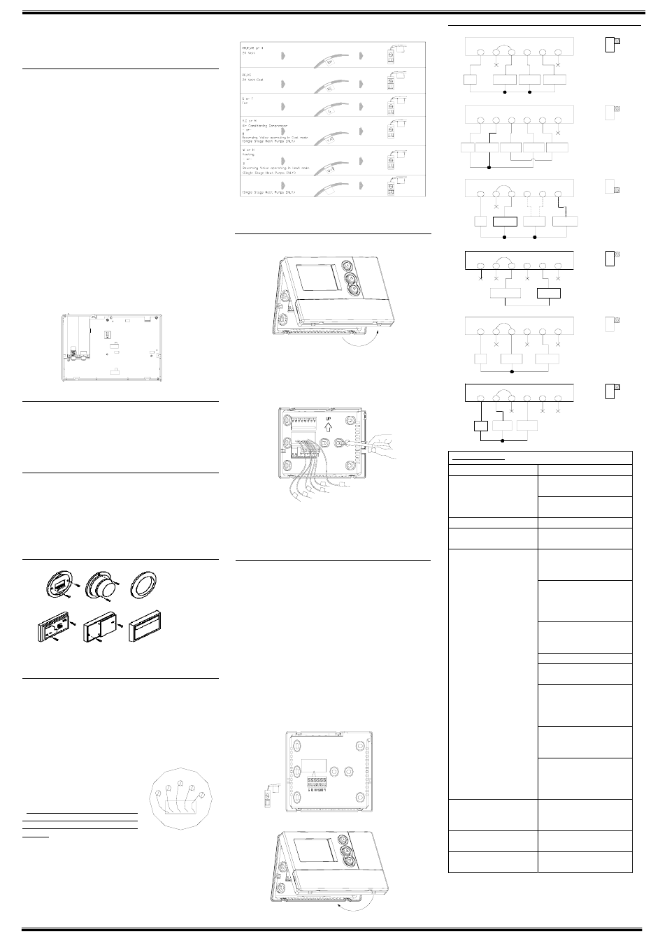
iring Diagrams
y Match and connect the labeled wires to the appropriate coded terminal screws on the
wallplate. (See Figure 4, 5.) Ignore any wires which may be present, but which were
note connected to the old thermostat.
y Refer to the Wiring Diagrams below to be sure your system is wired correctly.
y If your system is a single stage heat pump and uses an O or B wire, you must move
the System Selector switch inside the thermostat to the Heat Pump position. If you
have a normal furnace or electric system, leave the switch in the Standard position.
Refer to the System Selector section on the back for more information on this switch.
y Be sure to tighten the terminal screws securely, otherwise a loose wire could cau
operational problems with your system or thermostat.
y Push excess wires back into the hole to prevent interference when installing the
thermostat to the wallplate.
y Make sure the System Switch is set to OFF, and the Fan Switch is set to AUTO.
y Insert the bottom tabs on the thermostat body into the slots at the bottom of the
wallplate. Press the top of the thermostat body to snap it into the wallplate. Refer to
Figure 6.
NOTE: Do not force the thermostat onto the wallplate, as the terminal pins may be
damaged. If it does not snap properly, the thermostat may not work.
y Insert the two AA size alkaline batteries, observing the polarity marked inside the
battery compartment.
y Switch on the main power at the panel or furnace.
re5
Figure6
W
TROUBLESHOOTING
Problem Solution
1. Check battery connections and
batteries.
No Display
2. Move the battery out and wait for
e
about 1 minut
Entire Display Dims.
1. Replace Batteries.
Auto Fan Does Not Turn On
Properly.
G/HE selector to correct
1. Move H
position.
1.
unction switch is in
n (“HEAT” or
Check that the f
the correct positio
“COOL”).
2. There may be as much as 4-mintue
ay.)
delay before the system turns On –
wait and check. (Compressor
protection del
3. Check your circuit breakers and
switches to ensure there is power
to the system.
4. Replace batteries.
5. Make sure your furnace blower
door is closed properly.
6. I
pump system only
re the jumper
f your non-heat
uses 4-wires, be su
wire is installed between the Rh/B
and Rc /O terminals.
7. Check the position of the
Reversing Valve selector switch:
Standard or Heat Pump.
Heating or Cooling Does Not Go
8.
-stage heat
i
t
On or Off.
If you have single
pump, be sure the jumper wire is
nstalled between the Y and W
erminals.
Erratic Display
1. Move the battery out hold any key
then place the battery again. Then
reprogram.
If unit continues to operate in the
1.
it.
Off position.
Replace un
Thermostat permanently reads
“HI”, “LO”, or “E1”,
“E2”..
1. Replace unit.
If
r technical assistance.
T
er is 1-866-591-9898
you experience any other proble
he service numb
ms, call us fo
W
G
RH
RC
Y
12
3
4
RECOVERY ENABLE
DISABLE
System Selector
STD
HP
K6
JP1
Fan Option
HG
HE
K5
CENTIGRADE
FAHRENHEIT
Auto Recovery
Wall mounting Plate Thermostat Cover
Wall mounting Plate Thermostat Cover
Y1
Heat Pump compressor
Y1
RH
RC
G
Y/O
W/B
Y1
Y1
W/B
Y/O
Rh
Rc
G
RH
J um per
HP
STD
Fan
Relay
Fan
R elay
W allp la te
T erm ina ls
C ool
C ontactor
C ool 24V
S up ply
System
Selector
HP
STD
J um per
4-W ire Heat/Coo l System
5-W ire/Heat Cool System
Single-Stage Heat Pump System
2-W ire Heat Only System
3-W ire Heat Only System
3-W ire Cool O nly System
G
Rc
R h
Y/O
W/B
Y1
Fan
Relay
C ool
2 4V S up ply
H eat
2 4V S upply
Cool
C ontactor
H eat Relay
o r Valve
G
Rc
R h
Y/O
W/B
Y1
H eat Pump
2 4V S up ply
G
Rc
R h
Y/O
W/B
Y1
G
Rc
R h
Y /O
W/B
Y1
G
Rc
R h
Y/O
W/B
Y1
G
Rc
R h
Y1
W allp la te
T erm ina ls
J um per
Y/O
W/B
Fan
R elay
H eat /C ool
2 4V S up ply
Cool
C ontactor
H eat Relay
o r Valve
System
Selector
STD
HP
Fan
Relay
C om pressor
C ontactor
R eversing
Valve
W allp la te
T erm ina ls
System
Selector
HP
STD
W allp la te
T erm ina ls
N o Ju mp er
System
Selector
HP
STD
J um per
H eat
Mode
C ool
M ode
OR
H eat 24 V or
M illivo lt S upply
H eat Relay
o r Valve
W allp la te
T erm ina ls
J um per
System
Selector
HP
STD
W allp la te
T erm ina ls
System
Selector
H eat 24V
Sup ply
H eat R elay
o r Valve
Connect To Proper Reversing
Valve Terminal. See Table A