Dayton Audio RS1202A 1000 Watt Dual 12" Subwoofer System Assembled User Manual
Page 2
The RS1202 is available as a kit or fully assembled. In kit form, it can be assembled in less than 1 hour. The kit is fun and easy to as-
semble and will provide the bass you’ve been missing in your home theater or sound system.
Note: If you purchased the system pre-assembled please skip to the “Optimum System Equalization” section.
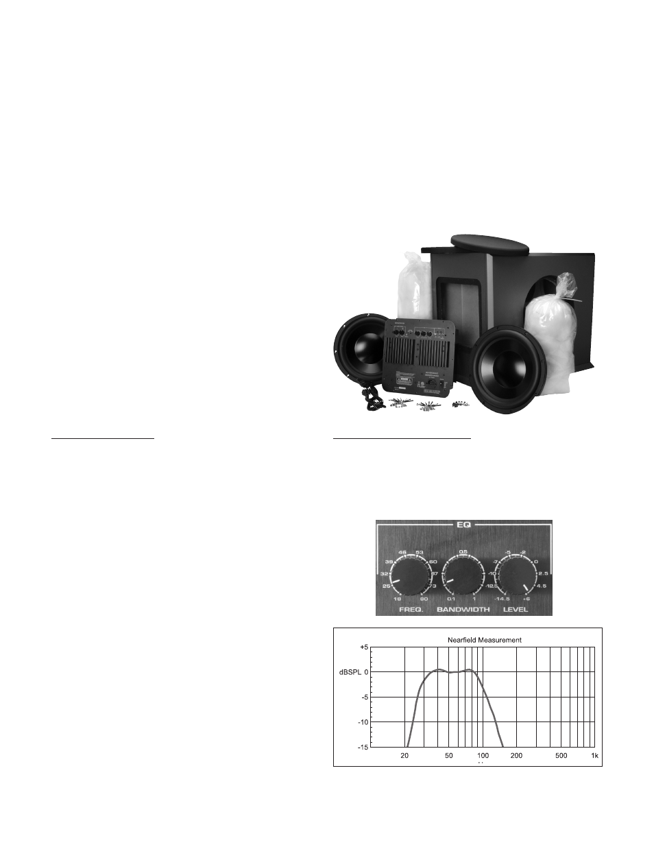
Parts Inventory
Your Reference Series RS1202 Subwoofer System should include the following:
• 1 Subwoofer cabinet
• 2 RSS315HFA-8 12" drivers
• 1 Subwoofer amplifier
• 2 1-lb. bags Acousta-stuf polyfill
• Cap head driver mounting screws
• Amplifier mounting screws (In amplifier box)
• 14 AWG wire
Installation Tools
The Reference Series Subwoofer System can be assembled with
the following tools and materials:
• Phillips screwdriver
• 5/32" hex driver
• Wire cutters/strippers
• Spray adhesive
• Utility knife
(2)
Thank You...for purchasing the Dayton Audio RS1202 Subwoofer System. It will fill almost any home with the deepest, loudest, lowest
distortion sub-bass imaginable. The opposed side-firing design ensures the 12" Reference Series drivers’ prodigious output excites your
senses and not the enclosure’s structure.
The RS1202 powered subwoofer is fully equipped with features that represent the kind of qual-
ity and performance that customers have come to expect from Dayton Audio, like:
• Parametric equalizer for optimum response and maximum
integration circuit eliminates harsh overload conditions and
protects drivers
• Low distortion, superior definition, and bone-rattling
output—flat response to 27 Hz
• Gray vinyl matches modern A/V furniture and accessories
Optimum System Equalization
The RS1202 was designed to deliver optimum results through the
use of carefully determined parametric equalization settings. The
intitial configuration, which will provide the specified performance in
most listening rooms, is set thusly—Frequency: 25 Hz, Bandwidth:
0.2, and Level: +6 dB. Variations are of course at the user’s discre-
tion; for more information about the parametric equalizer, please
review the Parametric Equalizer section as detailed on page 3.
• 2.1 cu. ft. true acoustic suspension cabinet
• Opposed side-firing drivers cancel cabinet vibration
• Heavily braced 1" and 2” MDF cabinet wall construction
• Dual high-Xmax Dayton Audio RSS315HFA-8 12" drivers
• Patented, ultra-efficient 950 watt RMS Class AB/Class G amplifier
• Auto on/off with standby mode
• User-adjustable gain and crossover frequency controls
Assembly Instructions
A. Install amplifier
Cut off connectors on amplifier output wires—be careful to leave
enough wire length to connect the speaker. Feed wire through
hole in divider. Insert amplifier into the back of the cabinet. The
amplifier features a thick foam gasket that provides an airtight
seal so no caulk is needed. Be sure to position the amp so
that the controls and printing are oriented correctly. Using the
supplied Phillips head screws, tighten down the amp in a “star”
pattern.
B. In
stall stuffing
“Fluff” and apply approximately 1.7 lbs of the supplied 2 lbs.,
using spray adhesive – remember to add stuffing behind the
window brace.
C. Install Drivers
Lay cabinet on one side. Be careful not to damage skirting!
Insert driver 1 (it doesn’t matter which side of the cabinet), align
holes and tighten screws. IMPORTANT: Match the mounting
flange holes to the threaded holes in the cabinet. Insert each
mounting screw one at a time and turn each by hand to start
the screw into the threaded hole in the cabinet. You may need to
move the driver from side to side to get each screw started.
Do
not tighten the screws until all the mounting screws have
been started by hand. Be careful not to cross thread the
screws! After all mounting screws have been started, tighten
the screws in a “star” pattern using a 5/32” hex driver. Carefully
lay cabinet on other side. Using the wiring diagram on page 3 as
a guide, strip amp wires and connect to driver 1 while observing
polarity. Strip supplied speaker wire at both ends and connect
to driver 1 while observing polarity. Connect remaining ends of
speaker wire to driver 2 while observing polarity. Insert driver 2,
align holes and tighten screws. Install the grills. You are finished
with the assembly of the subwoofer system. Be careful, the as-
sembled subwoofer system is very heavy!
Nearfield measurment with the following settings: Frequency = 25 Hz;
Bandwidth = 0.2; Level = +6dB; Low Pass Filter = 90 Hz.