Procom RH-900-... User Manual
Rh 900
RH 900/...
Hybrid Ring Combiner for 900 MHz Cellular Base Station
Transmitters
DESCRIPTION
The RH 900/… is a hybrid ring combiner providing the possibility of
operating two transmitters with very little or no frequency separation on
the same antenna.
The combiner forms part of the combining systems of cellular 900 MHz
base stations where multiple transmitters must be connected to a
common antenna.
The RH 900/… provides easy expandability as several devices can be
mounted in a row as shown on the figure below.
Materials used are aludine-treated aluminium, silvered brass and teflon.
The combiners are supplied with a coating of black, 2-component
polyurethane.
The RH 900/… is as standard provided with 7/16” connectors.
Combiners with other connector types may be quoted on request.
ORDERING DESIGNATIONS
CELLULAR SYSTEM
FREQ. (MHZ)
ORDERING DESIGNATION
NMT 900
TX: 935 - 960
RX: 890 - 915
RH 900/NMT-TX
ETACS
TX: 917 - 950
RX: 872 - 905
RH 900/ETACS-TX
EAMPS
TX: 869 - 894
RX: 824 - 849
RH 900/EAMPS-TX
SPECIFICATIONS
ELECTRICAL
FILTER TYPE
Hybrid Ring Junction
FREQUENCY
900 MHz cellular bands
MAX. INPUT POWER
500 W
INSERTION LOSS
Nom.: 3.01 dB
Typ.: 3.04 dB
ISOLATION TX
1
→ TX
2
35 dB at SWR
ANT
≤ 1.1
20 dB at SWR
ANT
≤ 1.5
IMPEDANCE
Nom. 50 Ω
SWR
≤ 1.25 with all other ports terminated
MECHANICAL
TEMP. RANGE
–30° C → +60° C
CONNECTORS
7/16''
LENGTH
180 mm excl. connectors
223 mm incl. connectors
WIDTH
36 mm
HEIGTH
194 mm
WEIGHT
Approx. 3.0 kg
MODE OF OPERATION
In the combiner the transmitting signals arrive 180° out of phase at each
others ports.This results in an isolation of more than 30 dB from one
transmitter to the other, which highly reduces the possibility of formation of
intermodulation products.
Normally, isolators provided with second-harmonic filters are inserted in
each branch between the transmitters and the combiner in order to increase
the isolation between the transmitters further, and to prevent
intermodulation caused by outside interfering signals entering the
transmitter output stages from the antenna port.
The inherent insertion loss of the combiner from each TX-port to the
antenna is 3 dB, which is inevitable when operating with very little or no
channel spacing. Half of the power of each TX is fed to the fourth port
where a suitably dimensioned 50 Ω load termination must be connected.
This termination is not supplied and it should have a VSWR not exceeding
1:1.1.
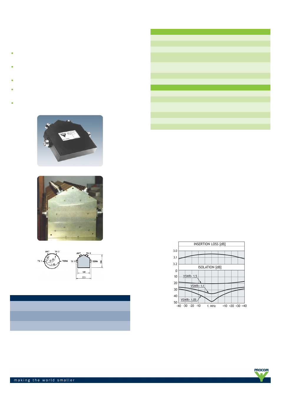
The isolation between the TX-ports is highly dependent on the VSWR on the
antenna port. At an antenna standing-wave-ratio of 1.5 the isolation will be
reduced to 20 dB (please, see the low curve).
TYPICAL RESPONSE CURVE