Procom GPS-COMBI MOUNT User Manual
Page 2
ELECTRICAL GENERAL SPECIFICATIONS
MODEL
GPS-COMBI MOUNT
ANTENNA TYPE
Active patch antenna
FREQUENCY
1575 MHz
IMPEDANCE
Nom. 50 Ω
POLARIZATION
Circular right-hand
COVERAGE
Hemispherical
GAIN
28 dBic in axial direction (typ.)
CROSS-
POLARIZATION ATT.
> 10 dB (typ.)
SELECTIVITY
> 45 dB down @ ± 45 MHz
BUILT-IN AMPLIFIER
GAIN
> 30 dB (typ.)
NOISE FIGURE
< 1 dB (typ.)
P
1 dB
Approx. +7 dBm
SWR (output)
<2.0
SUPPLY VOLTAGE
5 ± 0.5 VDC (3 V resp. 12 V on request)
CURRENT CONSUMPTION Approx. 25 mA
MECHANICAL (ONLY FOR THE GPS-PART)
MATERIALS
Cu-nite brass
Stainless steel
Reinforced thermoplastic
ANTENNA COLOUR
Black
TEMP. RANGE
-35° C →+75° C
CONNECTOR
FME (male for GPS) +
FME (female for mobile antenna)
RECOMMENDE
INSTALL. TORQUE
4 ± 0.5 Nm
DIMENSIONS (H x L)
Approx. 30 x 89 mm
ROOF THICKNESS
Max. 2.5 mm
WEIGHT
114 g
MOUNTING
ø18 mm dia. hole for roof thickness up to 2.0 mm
ø18.5 mm dia. hole for roof thickness 2.0 - 2.5 mm
Tools for mounting included
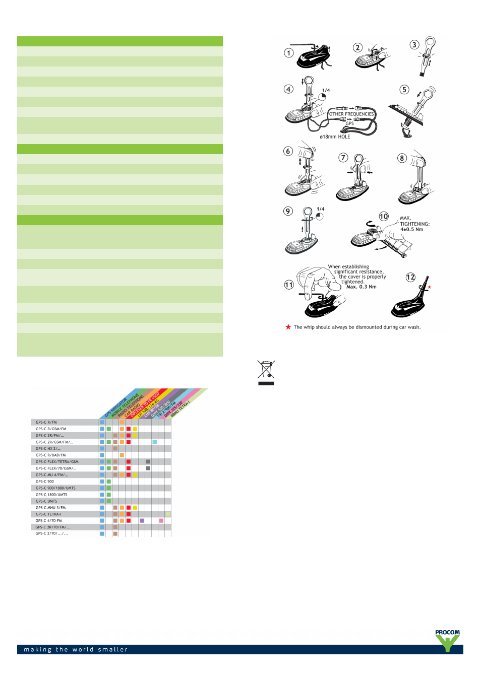
INSTALLATION
The various GPS-Combimodels can be connected to the following devices
MOUNTING INSTRUCTIONS
PROCOM A/S reserve the right to amend specifications
without prior notice.
15/01/14