Operation manual for digital deadbolt – Factory Direct Hardware Copper Creek HZE2630LF User Manual
Page 2
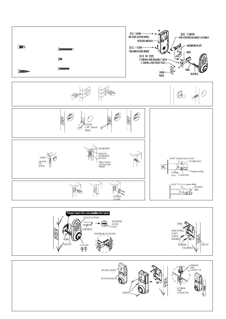
OPERATION MANUAL FOR DIGITAL DEADBOLT
EDA-33
A. DOOR &JAMB PREPARATION/LATCH INSTALLATION
B. INSTALLATION OF DEADBOLT ASSEMBLY
C. INSTALLATION OF RECEIVER MODULE
S1..FOR METAL DOORS
1/4”(6mm) 2 SCREWS-FOR DEADBOLT LATCH
1/4”(6mm) 2 SCREWS-FOR STRIKE PLATE
S2..FOR WOOD DOORS
3/4”(19mm) 2 SCREWS-FOR DEADBOLT LATCH
3/4”(19mm) 2 SCREWS-FOR STRIKE PLATE
S3..FOR DEADBOLT ASSEMBLY
FOR 5 PINS:
15/16”(24mm) 2 SCREWS-FOR 1-1/8”~1-3/8”(28mm~35mm) DOOR THICKNESS
1-1/4”(32mm) 2 SCREWS-FOR 1-3/8”~2”(35mm~51mm) DOOR THICKNESS
S4.5/16”(8mm) 2 SCREWS-FOR UPPER RECEIVER MODULE
S5. 1”(25mm) 1 SCREW-FOR LOWER RECEIVER MODULE
1. Mark Door
1) Use template provided to mark door for drilling 41”
(1044mm) from base of the door or 4”(101.6mm)
above door knob or lever center to center.
Use 2) Use the template to select backset 2-3/8”(60mm)
Or 2-3/4” (70mm).
2. Drill Holes
1) Bore 2-1/8”(54mm) hole through door face
from both sides of door to avoid damaging
door surface.
2) Drill 15/16”(24mm) or 1”(25.4mm) hole
through door edge.
3. Install Deadbolt Latch
1) Insert deadbolt latch into hole and mark
around the faceplate and screw holes.
2) Chisel recess for face plate.
3) Secure latch with screws.
4) Make sure the face plate of the latch
is even with edge of door.
4.Drill Holes And Install Strike Plate
1) Mark Jamb
a. Close door until deadbolt latch
touches door jamb.
Mark door jamb
as shown with
a pencil.
b. Center the strike plates
on the door jamb.
2) Mark Outline of Strike
a. Measure one half of
door thickness from
door stop and vertically
mark drill point center
for strike.
b. Place strike in position
and mark outline of
strike plate.
3) Drill Hole
a. Drill 1”(25.4mm)
hole in door
jamb
Caution: Hole in door jamb
must be drilled 1” (25.4mm)
deep.
5. Install Strike Plate
1) Chisel outline for strike plate 1.6”(4mm)
deep or until plate is flush with door jamb.
2) Install strike plate with screws.
ADJUST BACKSET FROM
2-3/8”(60mm) TO 2-3/4”(70mm)
A. Use provided torque blade or flat tip screwdriver
to rotate crank to retract the deadbolt to the
unlocked position.
B. Push the change lever up against the top.
Hold torque plate and torque spring and pull
the extention plate all the way out. Be sure
the 2-3/4”(70mm) screw hole is properly
aligned and change lever goes back to its
original position.
C. The deadbolt is now set for 2-3/4”(70mm)
backset.
1) Open door to ease installation.
2) Place exterior deadbolt assembly
on exterior of door,aligning
tailpiece horizontally through
deadbolt latch while passing the
wire under the deadbolt latch to
the interior side of the door.
Note:
1. Wire should be mounted under
the latch.
2. Tailpiece of exterior cylinder
should be inserted horizontally
through deadbolt latch hole first.
3) On interior side of door, place mounting
plate so the wire is routed up through
bridge in plate, and recess of
mounting plate is aligned with
center of large hole.
Note: Make sure mounting plate
is oriented with arrow pointing
upward.
4) Secure and fasten mounting plate
with screws (2) which engage with
threaded holes of exterior key cylinder.
Note: Ensure the mounting plate is
Positioned vertically.
1) Remove battery cover from receiver module by sliding cover upward.
2) Position receiver module over mounting plate so turnpiece engages with
tailpiece. Be sure the turnpiece is vertical in the unlocked position.
3) Check operation of the deadbolt by manually turning the
turnpiece or using the key. Bolt should extend and retract
freely. If bolt cannot be moved freely,the direction of
entry Switch is in the wrong place. Move receiver module
and turn the Entry Switch to the opposite direction.
Install again and check the operation of bolt.
4) Connect interior wire connector to exterior wire connector.
5) Secure receiver module to mounting plate,using the screws provided.
Do not over tighten screws, then put on Logo.
6) Install (4)
receiver module.