Poly-planar – PolyPlanar IMR-2 User Manual
Page 5
MRR-7 Keypad - IMR-2 Interface 9
————————————————————————————
Maryland USA (410) 761-4000 - www.polyplanar.com
poly-planar
Waterproof Marine Audio
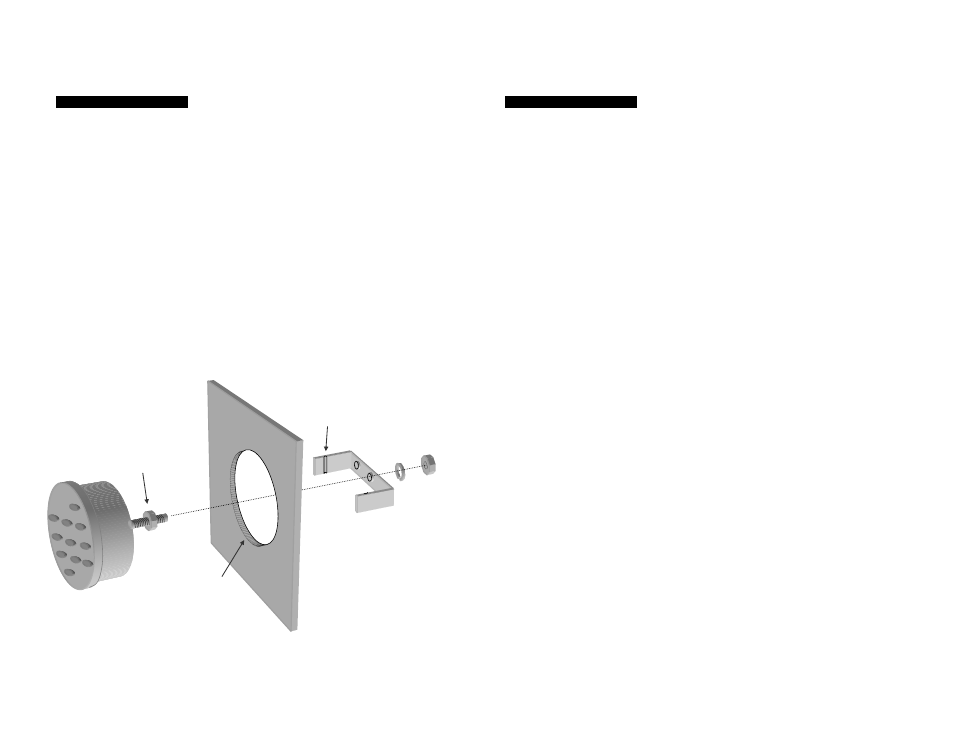
Mounting the MRR-7
10) The MRR-7 is designed to fit into a standard 2-1/8” (54mm) instrument
panel hole. If a hole is not already present then use a 2-1/8” hole saw
available at most hardware stores. Be sure that there is adequate
clearance behind the hole location and that there are no wires, cables,
or structural members in the way before cutting the hole. You will
need access to the back side of the mounting surface in order to
attach and tighten the mounting hardware for the MRR-7. (see figure
7) Do not over-tighten the mounting nut.
a. The secondary nut on the mounting stud should be adjusted to
allow the main nut to tighten against the bracket without
putting excess pull on the stud of the MRR-7.
b. In the case of a thick mounting surface, it may be necessary
shorten the aluminium mounting bracket by breaking the sides
at the 2 indentations.
(figure 7) Mounting the MRR-7
Mounting
Bracket
2-1/8 Inch
(54 mm)
Mounting Hole
Break here if
bracket is too
long
Adjust
secondary nut
MRR-7 Keypad - IMR-2 Interface 10
————————————————————————————
Maryland USA (410) 761-4000 - www.polyplanar.com
poly-planar
Waterproof Marine Audio
Mounting the IMR-2
11) IMR-2 should be mounted to a flat surface as close to the Audio
Center as possible. It should be mounted in an area that is free from
dripping water. There are 2 tabs on the plastic case that can be used
for screw mounting, or fix the unit using the included double-stick
tape. The cables should be dressed as neatly as possible and should
be kept clear of other vehicle wiring. Fold or coil any excess length of
the gray flat-cable. Long runs of audio cables can be very sensitive to
interference so care must be taken to route them away from high-
current carrying wires
Troubleshooting
12) MRR-7 Volume control buttons do not affect the Audio Center as
desired
a. Be sure that the Volume control mode switch [17] is slid
toward the ‘Radio’ position (right looking at rear of unit)
13) MRR-7 Volume control buttons do not affect the Zone Amplifier as
desired
a. Be sure that the Volume control mode switch [17] is slid
toward the ‘Zone Amp’ position (left looking at rear of unit).
b. Be sure that the Zone Amplifier is connected to it’s
corresponding Interface (IMR-11) at the Audio Center.
14) When I press the intercom button on the unit mounted in the cabin
(helm), the person at the helm (cabin) cannot hear anything.
a. If you tend to hear yourself when you use the intercom then it
is likely that the connection to the IMR-2 interface is incorrect.
Switch the connection to the opposite 8-pin DIN connector on
the IMR-2 and try again.
b. If you system includes a Zone Amplifier then be sure that the
2.5mm stereo jack [To Zone Amp] on the IMR-2 is connected
to the 2.5mm stereo plug [From Intercom] on the IMR-11