Data sheet, V100 – Procom V100 User Manual
Page 3
Data Sheet
V100
Amplifier Slide-in Panel
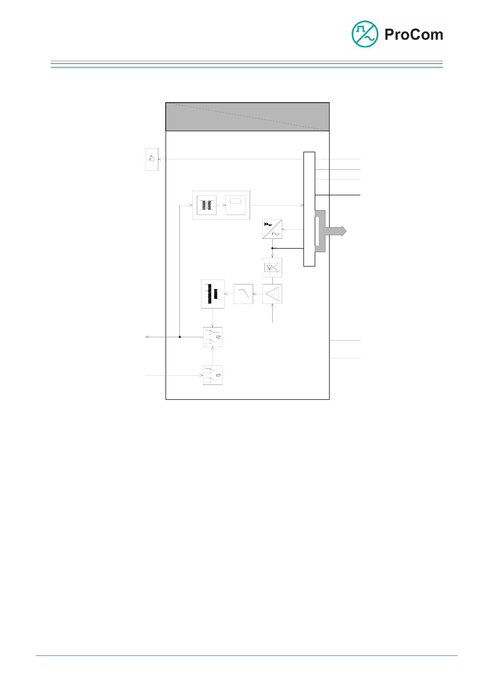
The following block diagram illustrates the functionality:
V100
BUS
S
t
e
u
e
r
g
P
KS
+5V
GND
-5V
-48V
+0V
u
n
C
M
(Z)
Impedanzüberwachung
Ausgangs-
rtrager
Übe
Codec
Testton
48V
rzschlussfest)
(Ku
Relais 1
50/70/100V
Relais 2
V out
VH in
Havarie-
Eingang
A
e
n
z
e
i
g
I
n
d
i
c
a
t
i
o
n
Meldung
Filter
NF
ital-
Verstärker
C
O
N
T
R
O
L
Potential-
trennung
Impedance Monitoring
Signal
P
C
M
Codec
LF
Test Signal
Potential
Sepera-
Output
Transformer
Impedance Monitoring
Dig
Digital
Amplifier
Impedance Monitoring
(Short-circuit Secure)
Relay 1
Disaster
Input
Relay 2
Block diagram V100
1) Control
A microprocessor regulates timing control between the PCM bus and the
module, controls message input and output and generates the audio signal re-
quired for impedance monitoring.
2) Codec
The codec converts the incoming digital signal into analogue LF and passes
this to the opto-coupler for potential separation.
3) Digital Amplifier
The digital amplifier amplifies the potential-separated LF signal.
The operating voltage of 48 V required for this is fused.
4) Filter
The low-pass filter filters the amplified signal and passes it on to the output
transformer.
Date:
16.03.2009 Page:
3/5 Author:
HS
Document-No.:
DB_V100_2510_01
© 2008 ProCom, All rights and technical changes reserved