Data sheet, 4npa, Ks bus +5v gnd -5v – Procom 4NPA User Manual
Page 3: 48v +0v
Data Sheet
4NPA
LF Interface Module
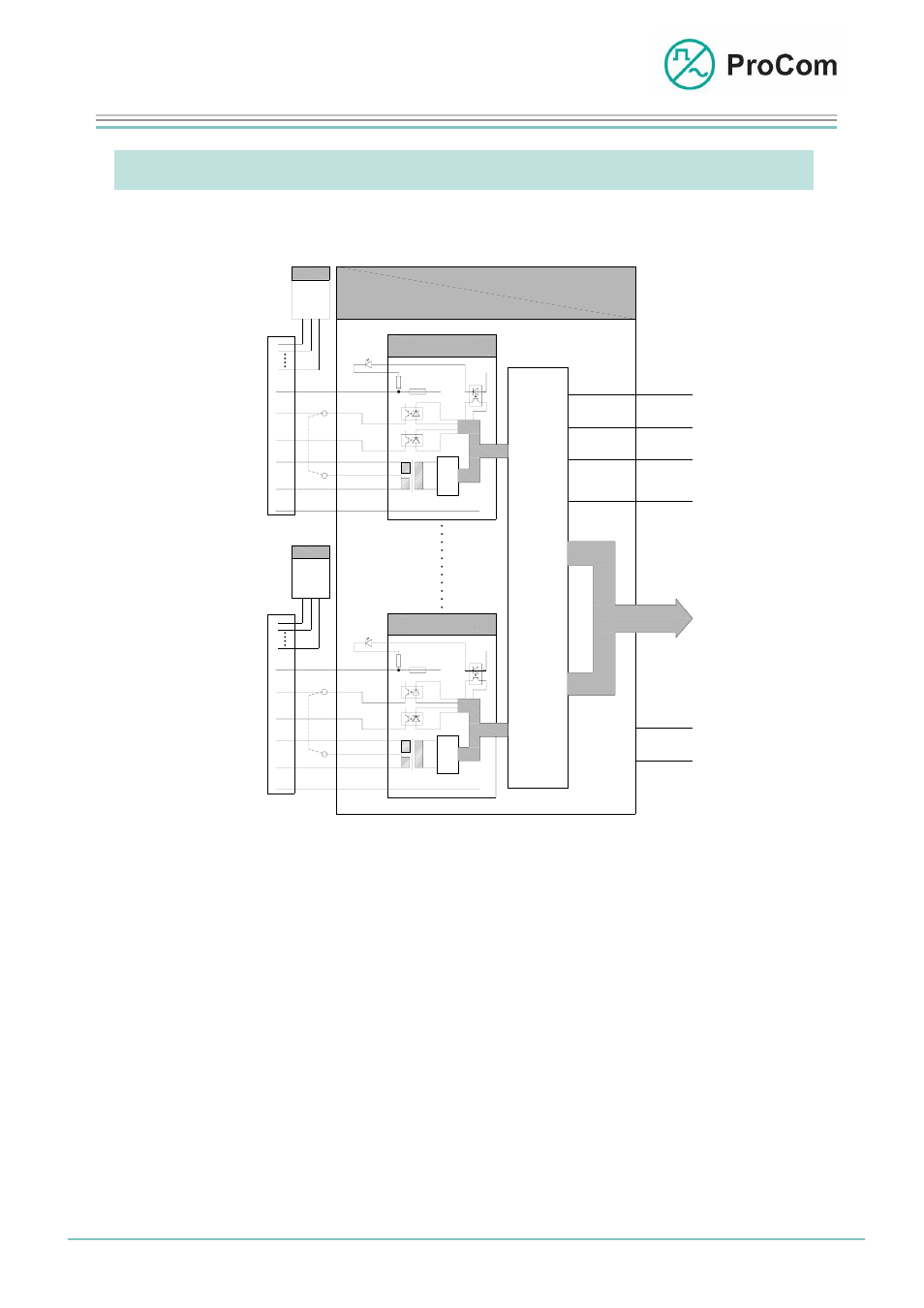
Function Description:
The principle functions are illustrated in the following block diagram.
4NPA
KS
BUS
+5V
GND
-5V
Satz 1
-48V
+0V
Satz 4
CO
DE
C
-48V
+
+
S
t
e
u
e
r
u
n
g
+
-
CO
D
E
C
+
Lb
La
-48V
+
+
S
p
r
e
c
h
s
t
e
l
l
e
-V
C
-
+
-
1
2
n
S
p
r
e
c
h
s
t
e
l
l
e
+
Lb
La
S
p
r
e
c
h
s
t
e
l
l
e
-V
C
-
1
2
n
S
p
r
e
c
h
s
t
e
l
l
e
24LI
24LI
Linien 1 - n
Linien 1 - n
Line 1 - n
C
A
L
L
S
T
A
T
I
O
N
Set 1
C
O
N
T
R
O
L
Line 1 - n
C
A
L
L
S
T
A
T
I
O
N
Set 4
Block diagram 4NPA
The 4NPA has four identical sets.
The -48 V output is fused with a cut-out fuse. If this is defective then a signal is
generated through an opto-coupler.
The C point is required for switching on the call station amplifier. To use one less
line, this can be switched using a solder bridge on the backplane over the mid-a/b
output transmitter.
The microphone amplifier of a third-party call station can be switched on and off
over the V point.
These points are switched using the ICS software.
The C and -V points are control requirements for third-party call stations. They are
galvanically isolated by opto-couplers from the control circuit.
The La/b are connected to the output transformer. The incoming or outgoing ana-
logue LF signal is converted analogue/digital by the codec.
Date:
13.03.2009 1 Page:
3/5 Author:
HS
Document-No.:
DB_4NPA_2320_01
© 2008 ProCom, All rights and technical changes reserved