Data sheet, 4lsl, Messkreis – Procom 4LSL User Manual
Page 3
Data Sheet
4LSL
Loudspeaker Function Card
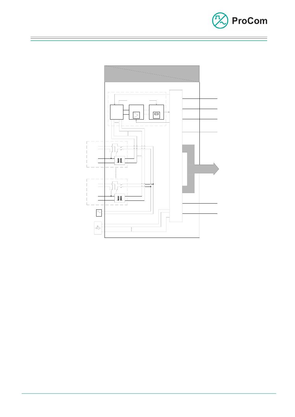
The principle functions are illustrated in the following block diagram.
4LSL
BUS
A
n
z
e
i
g
e
S
g
t
e
u
e
r
u
n
MUX
2
U
I
P
C
M
KS
+5V
GND
-5V
-48V
+0V
Messkreis
Measuring Circuit
x 4- Kanal
Mess-
verstärker
Mess-
auswerter
(Z)
U
I
Kopplung
U
I
LK 1
V 1
(V100)
C
O
N
T
R
O
L
Coupling
Msgmt.
Amplifier
Msgmt.
Evaluator
2 x 4-
Chanel
Satz 1
U
I
LK 1
V 1
(V100)
Satz 4
TG01
G
U
I
U
I
Set 1
Set 4
I
n
d
i
c
a
t
i
o
n
Block diagram 4LSL
The 4LSL consists essentially of a control unit, a measuring circuit and 4 inde-
pendent sets. Each set has a low frequency (LF) input (usually from the V100
amplifier) and a loudspeaker output.
Required for the impedance measurement is the measurement signal generated
by the TG01. Locking by the relay ensures that only one action can be carried out
on the set, and that the LF signal does not reach the TG01. The measurement
signal (125 Hz) is given on the loudspeaker circuit. The current flowing there is
added to the measurement circuit through an input transformer and analysed to-
gether with the output voltage. All processes are controlled through configurable
programmes in the ICS software.
For a public address system the LF signal is added to the loudspeaker circuit
through an output transformer.
Displays and messages are regulated by the control unit.
Public address and testing
in a loudspeaker circuit are blocked off from one an-
other. Public address has higher priority; a test is carried out after a public ad-
dress.
Date:
13.03.2009 Page:
3/7 Author:
HS
Document-No.:
DB_4LSL_2830_01
© 2008 ProCom, All rights and technical changes reserved