S0-attachment, 4ftr, S0- aufsatz – Procom S0 Attachment User Manual
Page 2: Data sheet, S0 attachment, Bus p c m
Data Sheet
S0 Attachment
S0 Attachment for 4FTR and LCPU
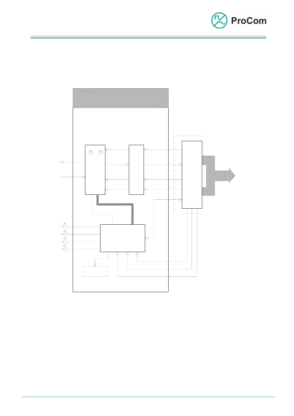
The following block diagram illustrates the way the S0 attachment for 4FTR or LCPU
functions.
FRM
CLK
4FTR
IOM2
CLK
FRM
Digital Upload
DU
DD
Digital Download
F
P
G
A
Slip
Buffer
Display
LED1
LED2
S0- Aufsatz
BUS
P
C
M
S0-
Modul
µ- Prozessor
RST
UART
R
x
T
x
S0
B
u
s
C
P
U
STO
Digital Output
Digital Input
STI
8k
10MHz
RST
PCM32
UART
indication 4FTR
indication 4FTR
indication 4FTR
indication 4FTR
S0-Attachment
Block diagram for S0 attachment
The FPGA regulates the S0 flow of data between the S0 attachment and the
BusCPU on the 4FTR or LCPU. Here the BusCPU is the interface to the DVS-21 and
the S0 attachment the interface to the outside world.
The microprocessor controls the other functions such as e.g. LEDs on the 4FTR.
The display is an aid to programme the telephone numbers for the person doing the
commissioning.
Date
20.08.2008 Page:
2/10
Author:
HS
Document-No.:
S0_DB_2870_01
© 2008 ProCom, All rights and technical changes reserved