Data sheet, 24li – Procom 24LI User Manual
Page 3
Data Sheet
24LI
24 Line Module
Function Description:
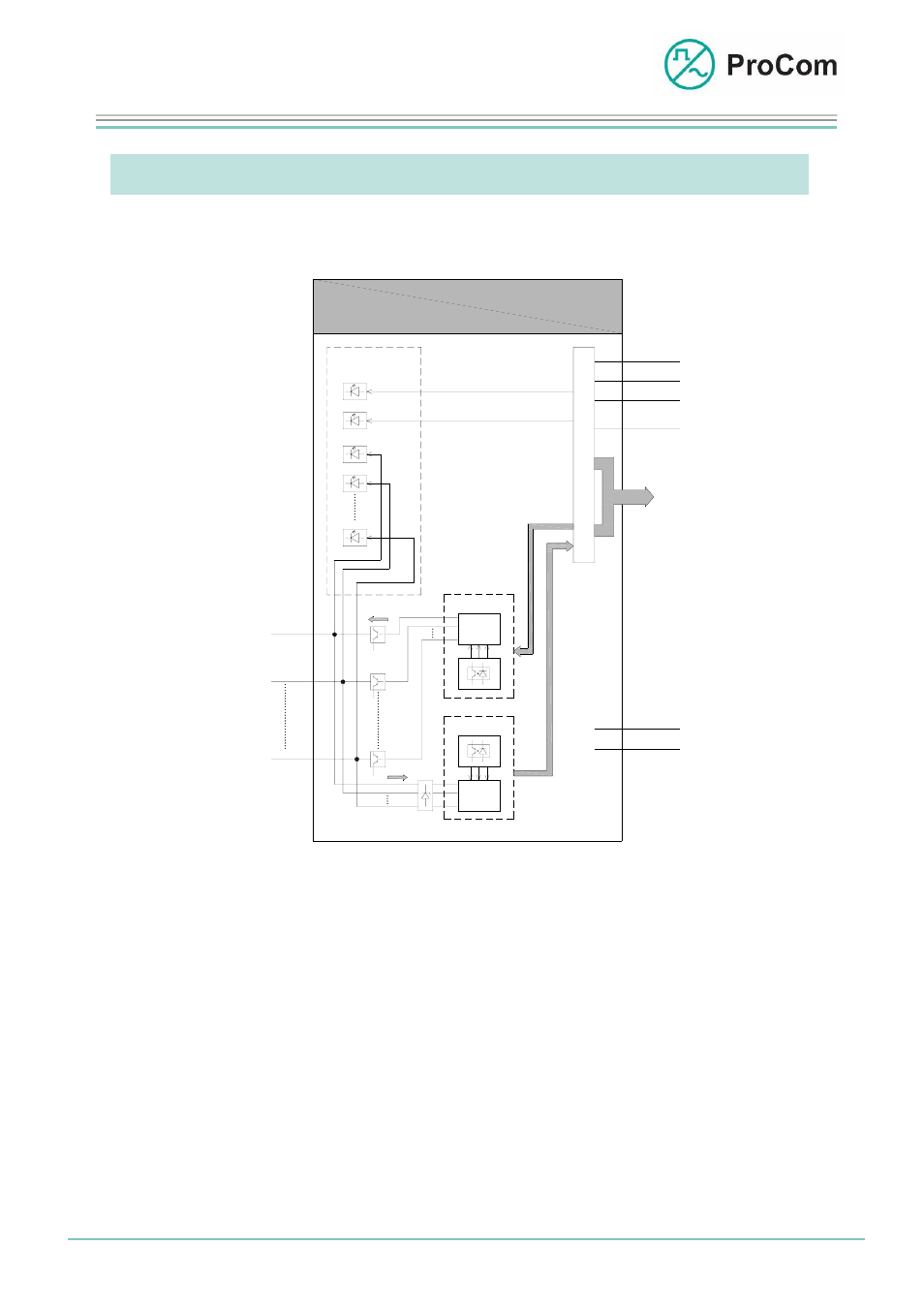
The principle functions are illustrated in the following block diagram.
24LI
-48V
+0V
MUX
3 x 8 - Kanal
Anzeige
Linie 01
Linie 02
I/O
System-
blinker
S
t
e
u
e
r
u
n
g
KS
+5V
GND
-5V
Linie 24
01
02
24
01
02
24
MUX
3 x 8 - Kanal
BUS
P
C
M
+0V
Linie 01
Linie 02
Linie 24
Output
Input
+0V
+0V
5V
5V
5V
Indication
System-
blinker
C
O
N
T
R
O
L
I/O
Line 01
Line 02
Line 24
Output
Line 01
3x8 channel
Line 02
Intput
Line n
3x8 channel
Block diagram 24LI
The 24LI has 24 independent bi-directional inputs/outputs.
These lines are configured using the ICS software.
Input and output status is displayed for each line by an LED on the front plate.
The reference potential is earth or 0 V.
The output idle voltage of the lines corresponds to the system operating voltage,
i.e. type -48 V.
-24 V (optional) to a max. -60 V can be switched in.
An active line puts through 0 V as output or is 0 V as input.
The line current is a maximum of 150 mA. The line is switched off in the case of
excessive load.
Date: 25.03.2009
Page:
3/4 Author:
HS
Document-No.:
DB_24LI_2824_01
© 2008 ProCom, All rights and technical changes reserved