3 installation, Installation procedures – Crown Audio P.I.P.-PA User Manual
Page 6
P.I.P.–PA
Page 6
3 Installation
Before installing this
P.I.P.
mod-
ule, you’ll want to configure it.
1. Set the microphone phantom
power jumper of each chan-
nel to the desired position. The
on/off positions are labelled
on the circuit board (see Fig-
ure 2.1).
2. Set the microphone low-cut
filter jumpers of each channel
to the desired position. The
on/off positions are labelled
on the circuit board (see Fig-
ure 2.1).
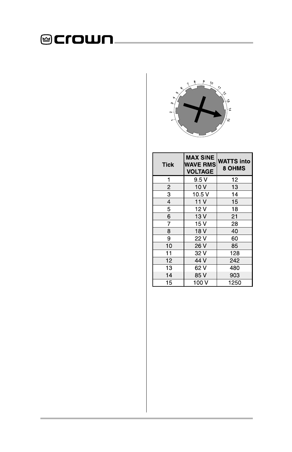
3. Adjust the compressor thresh-
old of each channel. A fifteen-
mark scale is printed on the
circuit board (see Figure 2.1)
which corresponds to the typi-
cal threshold settings shown
in the table in Figure 3.1.
Now you are ready to install the
P.I.P.
in the amplifier.
Fig. 3.1 Compressor Threshold
Settings
Note:
These voltage and power levels
are valid only for Stereo (Dual) and
Parallel-Mono modes of operation. The
voltages shown must be doubled and
the power levels recalculated for
Bridged-Mono mode.
Also note:
The maximum output power
is strictly limited to the capability of your
amplifier. Any threshold setting above
the maximum output power of your amp
will result in the compressor acting solely
as a “clip” eliminator.
Installation Procedures
You may need a Phillips screw-
driver to remove the existing
P.I.P.
module or panel from your ampli-
fier.
CAUTION:
Before connecting
this or any
P.I.P.
to your amplifier,
it is important to turn its level
controls down, turn it off and re-
move the AC power. Don’t touch
the circuitry. Even though the