Factory Direct Hardware LCN SEM7840 User Manual
Caution, Fig. 3, Fig. 2
SEM 7840/7850
Sentronic Electro-Magnetic
Single Door Holder Concealed Wall Mount
®
®
1-800-526-2400
2/07 © 2007 SCHLAGE LOCK Company. All rights reserved D.P. # 29352r2
IMPROPER INSTALLATION MAY
RESULT IN PERSONAL INJURY OR
PROPERTY DAMAGE. FOLLOW ALL
INSTRUCTIONS CAREFULLY. FOR
QUESTIONS, CALL LCN AT
800 - 526 - 2400
CAUTION
!
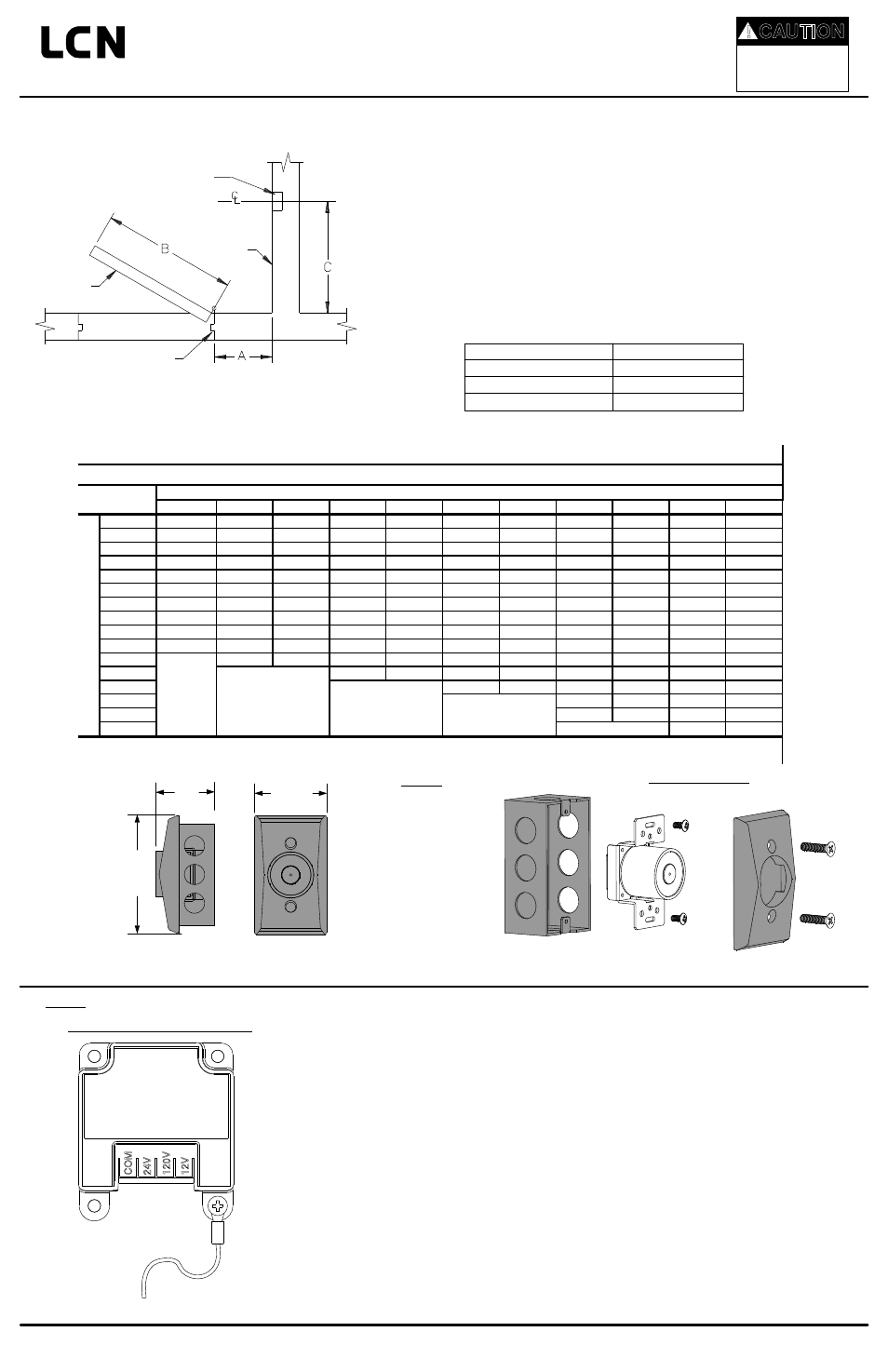
JUNCTION
BOX
WALL LINE
DOOR
DOOR JAMB
Step 1: Locate the Junction Box (Not Provided)
A.
B.
C.
D.
See Fig. 1. Measure dimensions A and B. Find the intersection of those two dimensions in
Table 1. The intersection is dimension C, the centerline of the surface mount box location.
(For 180° installations, take B dimension and subtract 5 5/8” to find the centerline of junction
box. Note: Optional extensions maybe needed.)
If dimension A or B is not shown on the chart, interpolate to find dimension C as follows.
If dimension A is 11” and dimension B is 36”, then:
dimension C = 33 - ((33 - 32 1/2)/2) = 32 3/4
If dimension A is 12” and dimension B is 35”, then:
dimension C = 32 1/2 - ((32 1/2 - 30 3/8)/2) = 31 7/16
If dimension A or B is beyond those listed in Table 1 or if they intersect in a blank area in
Table 1, use optional extensions as needed to align contact plate and magnet.
See Fig. 2. The center of the junction box should be located about 5” from the top of the
door. Install junction box to withstand at least a 50 pound pull.
Pull wire in accordance with applicable codes, standards, and authorities having jurisdiction.
Electrical specifications are shown below.
WALL PORTION
2 13/16”
70mm
2 ½”
64mm
4 5/8”
117mm
Step 2: Install the Magnet
A. The magnet is shipped partially assembled for protection. Unscrew the cover from the
magnet bracket assembly. Keep the screws for later reattachment.
B. See Fig. 3. Connect the supply earth ground wire to the green wire on the magnet bracket assembly. Connect
the power supply common wire to the screw terminal marked COM. If the supply voltage is 24V, connect the
power supply hot wire to the screw terminal marked 24V. If the supply voltage is 120V, connect the power
supply hot wire to the screw terminal marked 120V. If the supply voltage is 12V, connect the power supply
hot wire to the screw terminal marked 12V. Polarity is important on the 12V input. There are protective plastic
tabs over the terminal screws. Break off the two tabs that protect COM and the desired voltage so that the
screw heads are exposed.
C. See Fig. 2. With the magnet wired, position the magnet bracket assembly into the junction box and attach it
to the box using the (2) 6-32 screws. Tighten firmly. Attach the cover housing using the (2) 10-24 screws from
step 2A.
COM
24V
120V
12V
Earth Ground
Back view of magnet assembly
Fig. 3
Junction
Box
Magnet
Bracket
Assembly
Cover
Fig. 2
28
30
32
34
36
38
40
42
44
46
48
2
26 1/8
28 1/8
30 1/8
32 1/8
34 1/8
36 1/8
38 1/8
40 1/8
42 1/8
44 1/8
46 1/8
4
26
28
30
32
34
36
38
40
42
44
46
6
25 3/4
27 3/4
29 13/16
31 13/16
33 13/16
35 5/8
37 7/8
39 7/8
41 7/8
44
46
8
25 5/16
27 3/8
29 7/16
31 1/2
33 1/2
35 1/2
37 5/8
39 5/8
41 5/8
43 5/8
45 11/16
10
24 3/4
26 13/16
29
31
33
35 1/8
37 3/16
39 1/4
41 1/4
43 5/16
45 3/8
12
24
26
28 1/4
30 3/8
32 1/2
34 9/16
36 11/16
38 3/4
40 13/16
42 7/8
45
14
23
25 3/16
27 3/8
29 5/8
31 3/4
33 15/16
36
38 1/8
40 1/4
42 5/16
44 3/8
16
21 5/8
24
26 3/8
28 5/8
30 7/8
33
35 1/4
37 7/16
39 9/16
41 11/16
43 13/16
18
20 1/8
22 3/4
25 1/8
27 1/2
29 13/16
32 1/8
34 3/8
36 9/16
38 3/4
41
43
20
18 1/4
21
23 11/16
26 3/16
28 5/8
31
33 5/16
35 9/16
37 13/16
40
42 1/4
22
19
22
24 5/8
27 3/16
29 11/16
32
34 7/16
36 3/4
39
41 5/16
24
22 3/4
25 1/2
28 1/8
30 11/16
33 1/8
35 3/16
38
40 1/4
26
26 3/8
29
31 11/16
34 5/8
36 5/8
39
28
30
32 5/8
35 3/16
37 11/16
30
28
30 7/8
33 9/16
36 3/16
32
31 11/16
34 1/2
A
=
D
im
e
n
s
io
n
o
f
d
o
o
r
ja
m
b
to
w
a
ll
(I
n
c
h
)
Nearest Whole
Number
B = dimension of door width (Inch)
Magnetic Door Holder Placement Chart
7840/50
Table 1
Input Voltage
Current Draw Max.
120VAC, 60Hz
24VAC, 60Hz/24VDC
12VDC
.02A
.02A
.03A