Wood screw mounting, Thru bolt mounting, Fig. 5 fig. 6 – Factory Direct Hardware LCN SEM7830 User Manual
Page 2: Install armature fig. 4
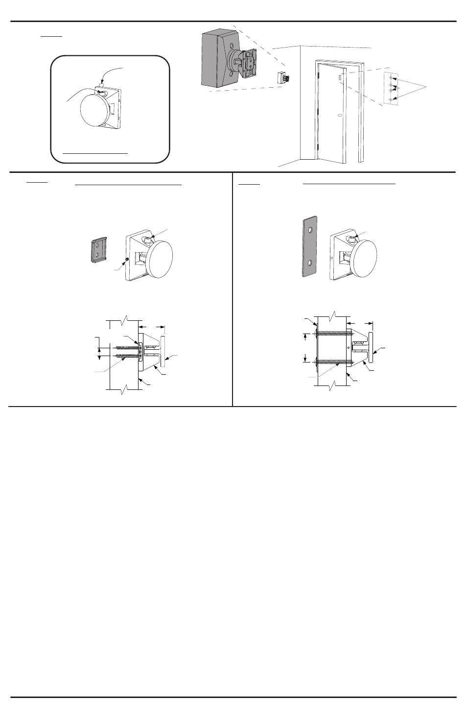
Step 3: Install the Door Armature
A. See Fig. 4. Slightly loosen the contact plate locking screw using a 5/32 Allen wrench so the contact plate can rotate with some
resistance. Remove the protective paper from the drill template sticky-back label on the back of the door armature.
B. Place the armature against the floor magnet. This is best done with power applied to the magnet. If power is not available, hold
the armature in place by hand. The armature contact plate must fully cover the magnet. If the contact plate is not centered and
flat on the magnet, reduced holding force will result.
C. With the armature against the magnet, open the door and press it against the armature and magnet. Pull the door away to transfer
the drill template to the door.
D. See Fig. 5 and 6. Determine if the armature will be mounted using the wood screw kit or the thru bolt kit. The thru bolt kit
is recommended for 1
hollow metal, hollow core, or composite-type wood doors. If using the wood screw kit, drill the center
two holes on the template using a 1/8 bit by 1
deep. If using the thru bolt kit, drill the outer two holes on the template using
a 5/16 bit all the way through the door. Remove the template after the holes are drilled.
E. Attach the armature to the door using the appropriate plate and screws. If using the wood screws and backup plate, tighten the
armature set screw against the backup plate as the last step using the 1/16 Allen wrench provided.
”
¾”
”
¼”
”
”
Template may need assistance with transferring to door, using a flat blade screwdriver on the
template tab that sticks out and push it onto the door while pulling the door away.
WOOD SCREW MOUNTING
FOR SOLID WOOD CORE DOORS
This view shows the contact plate
locking screw accessible from the top.
Rotate backup plate 180° for underside access.
THRU BOLT MOUNTING
RECOMMENDED FOR
HOLLOW METAL, HOLLOW CORE
OR COMPOSITE TYPE WOOD DOORS
Contact Plate
locking screw
Door
Plate
Armature
Contact Plate
locking screw
Backup
Plate
Armature
Set
Screw
Fig. 5
Fig. 6
Locking
Screw
For drill hole template,
remove paper from
the back to reveal
sticky back of template.
Install Armature
Fig. 4
Thru
bolts
Wood
Screws
Backup
Plate
Door
Plate
Contact
Plate
Contact
Plate
Pull Side
of Door
Pull Side
of Door
Armature
Armature
(2) #10 x 1 ½”
(2) 1/4-20 x 2”
½”
13mm
1 5/8”
41mm
1 5/8”
41mm
1 3/4”
44mm