Factory Direct Hardware Von Duprin 9827EO4 User Manual
Page 4
Shim
(as needed to
engage latch)
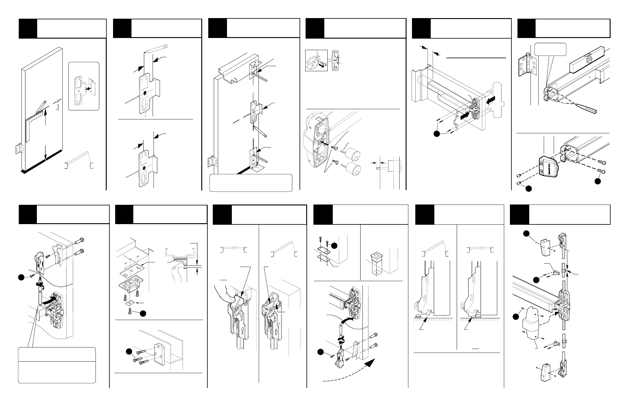
5
6
Install trim (if using) and
secure device center case
to door.
Install mounting bracket
and end cap.
7
Install top latch and rod.
Top
latch
Top rod
(longer of
the two)
If top rod is too long, see “cut
top rod” on page 6
Install top strike.
299/299F strike
8
#
325 sex
bolts
(required)
Strike plate
(299 only)
260U strike
3/16”
9
Install bottom strike,
latch, and rod.
11
Adjust bottom rod with
door open (top latch
retracted).
Open and close door a few times
and check for deadlatching when
door is closed
Readjust rods if needed
Adjust top rod (screw
rod into or out of latch)
until adjusted as shown.
9
10
248L-4 strike
304L strike
Grout strike
into floor
With door
closed:
With door
open:
Latch bolt
should clear floor
and not bind on
strike
With door
closed:
With door
open:
Bottom
latch
Bottom
rod
#325
sex bolts
(required)
Door open
(top latch retracted)
2
Align top and bottom
templates along center
line, and prepare door
.
3
Position template as shown
and mark vertical C.
Or flip template over for:
1
RHR shown
(LHR opposite)
Draw horizontal center
line (C ) and assemble
device template.
Bottom
template
CL
39-5/8”
To finished
floor
Shim
to 3/16”
as shown
L
Latch bolt
deadlocked
(will not push in)
Latch bolt stays
retracted
Release
trigger
extended
Latch bolt
should be
deadlocked
(will not push in)
If top rod is too short, see
“install rod extension”
on page 6
Secure
mounting
bracket
and end cap
Mounting
bracket flush
Level device
Mark and prepare 2
mounting holes
See “Preparation Chart” on page 3
for preparation information
Device
template
Install rod guides, and covers.
12
Latch
cover(2)
*Rod
guide (2)
Center
case
cover
Install at
midpoint of
each rod
4
5
*See “Preparation
Chart” on page 3
CL
CL
See “Preparation Chart” on page 3 for
drill, tap, and cut-out information
2-3/16”
Standard
backset
For 9927
single and
double
door
2-3/4”
backset
If using a
9927 with a
9975 mortise
device on a
double door
CL
CL
Center
case
See “Screw Chart”
on page 2 for screw
types and sizes
A
B
C
D
E
F
G
D
H
I
J
CL
CL
CL
Vertical
L
Remove blue film
Top
template
Plastic
template
See trim instructions for pull side door
preparation. Line X-X in trim instructions
is same as vertical device CL
Trim
(optional)
1-1/2” Minimum clearance
(with end cap removed)
if device is too long for
door, see “Cut Device”
on back cover
Cut tailpiece
if needed
1/2”
Door
surface
4
Tailpiece
Tailpiece guide
Rotate tailpiece
guide to match
tailpiece
If using an outside cylinder,
check NL drive screw and
install tailpiece guide.
When installing trim that has a
functional lever, knob, or thumb
piece AND an outside cylinder
to lock and unlock the trim,
remove NL drive screw from
back of device.
DO NOT remove NL drive
screw for the following trims:
NL, EO, DT, TP-2, L-2, and K-2.
With “BE” trim, device may
need rehanded. Look for
instructions on back of trim.
Note: When the
NL drive screw
is left in back of
device, the outside
cylinder will
function only
as a Night Latch.
NL drive screw
499F strike (for LBR Fire devices)
See instruction 911009