Neutrik NPPA-TT-E90 PATCH PANEL User Manual
Page 6
Page 6 of 14
NPPA-TT-E90 Instruction Manual
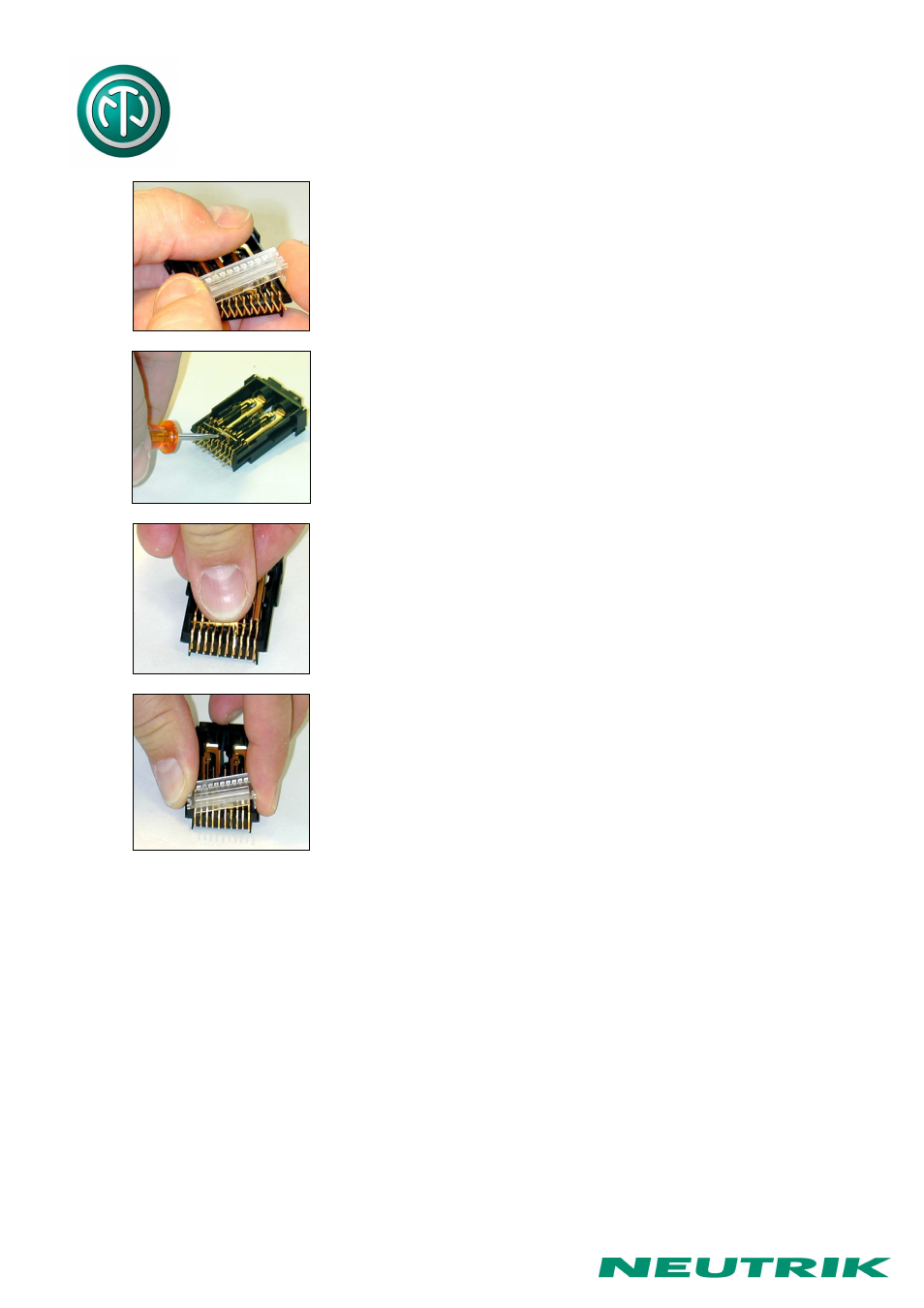
Then remove the cover with a tiny grip at the side and carefully
Pull out the configuration bars you need to exchange
(preferably using a small screw-driver).
Insert new bars carefully by pressing them in parallel at both
ends.
Attention: To ensure best contact conditions never reuse the
configuration bars once being put in place! Always take new
ones! Keep the contacts and switches in place with the thumb
while manipulating the normalling contacts.
Finally snap on the cover (Insert it first at one side and then
snap slightly into the opposite groove with a light pressure on
the nose).
4. Grounding variations
The flexible grounding system provides the following versions:
Individual:
Each channel is individually grounded by its corresponding cable shield
(default configuration).
Group:
Selected channel grounds are connected via the ground bus on the
PCB using solder bridges and track cuts to form a group that is
connected to one common cable shield.
Central:
All channel grounds (individual top and bottom row) are connected via
the ground bus on the PCB using solder bridges and wired with only
one cable shield.
Chassis-Common:
The same as central grounding but with the addition of the common
ground bus (top and / or bottom rows) connected to the patch panel
chassis by means of jumpers.