3B Scientific Stirling Engine D User Manual
Page 5
5
1 3B NETlab™ program
U11310
1 Relative pressure sensor, ±100 hPa
U11321
1 Displacement sensor
U11371
1 DC power supply, 15 V, 1.5 A (230 V, 50/60 Hz)
U8521121-230
or
1 DC power supply, 15 V, 1.5 A (115 V, 50/60 Hz)
U8521121-115
•
Connect the relative pressure sensor to the
hose nozzle using silicone tubing.
•
Attach the base plate to the stand using the
knurled screw.
•
Screw the stem with the magnetic base into the
displacement sensor and place it on the base
plate.
•
Loosen the screw on the displacement sensor’s
pulley. Wind a thread once around the pulley
and lead it out of the recess placing a loop
around the screw. Use the screw to fix the
thread in place (see Fig. 8).
•
Attach one end of the thread to the hook of the
connector rod and suspend a weight from the
other end.
•
Use the suction pad to attach a second thread
to the base plate. Thread this over the groove
in the eccentric and use the other weight as a
load on the free end.
This load ensures that the pV diagram comes out
better.
Fig. 8 Schematic illustration of how the thread is wound
around the pulley of the displacement sensor (U11371)
•
Connect the power supply to the heater plate
and set the voltage up to 12 V (1.5 A approx.).
•
Connect both sensors to the 3B NETlog™ inter-
face.
•
Run the software on a computer.
•
After the Stirling engine has heated up, start it
running by pushing the rotor in a clockwise di-
rection.
•
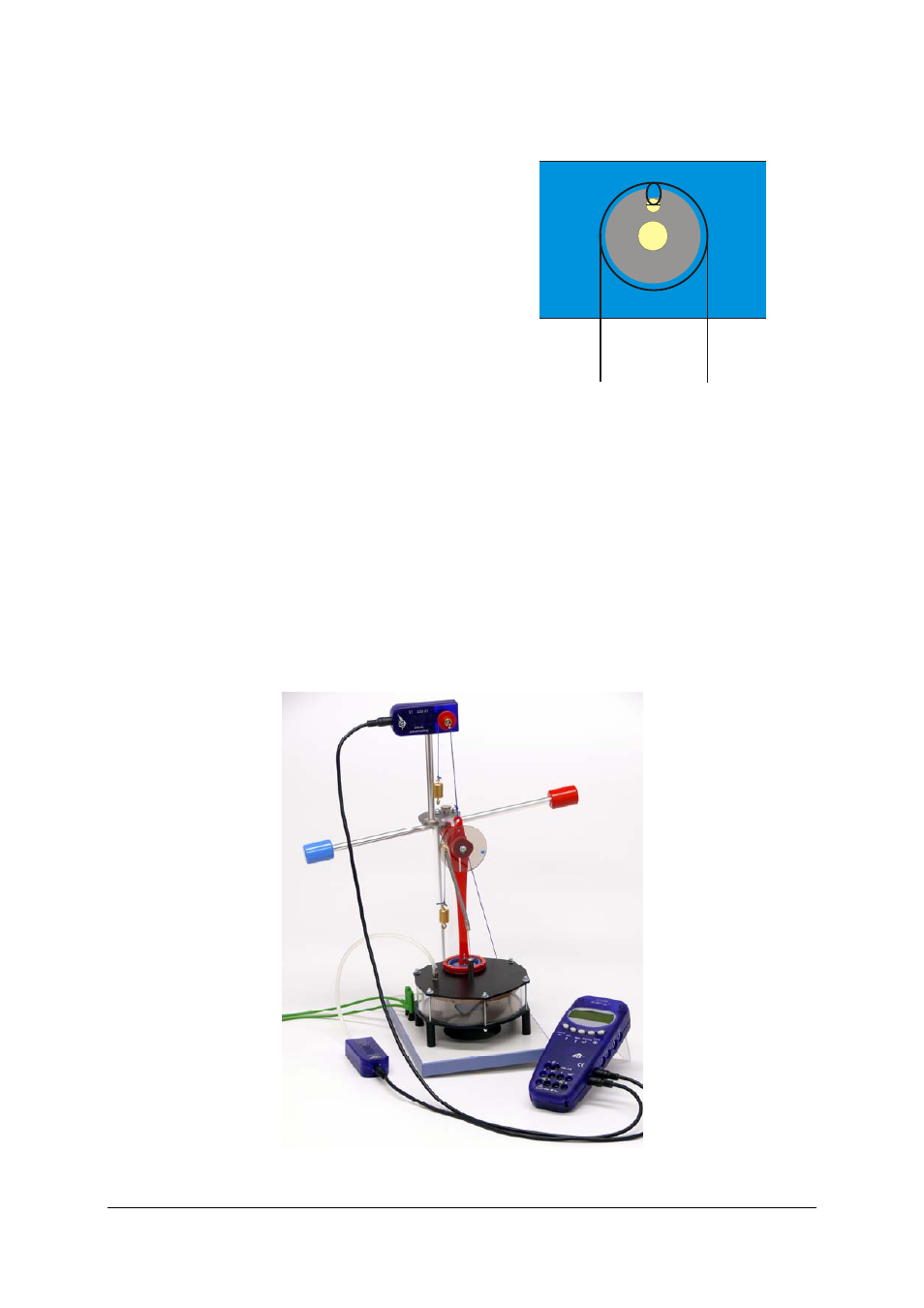
Start a measurement using the software and
evaluate the data.
Fig. 9 Experiment set-up for recording a pV diagram