3B Scientific Dual Pole Tube User Manual
Page 2
2
4. Technical data
Cathode area:
approx. 32 mm²
Max. anode voltage:
400 V
Heater voltage:
1.5 – 5 V
Heater current:
2 – 5 A
Tube dimensions:
approx. 120
×45 mm²
Overall dimensions:
approx. 170x105x230mm³
Weight:
approx. 370 g
5. Operation
•
Carefully push the tube into the two middle
sockets of the base and connect the anode lead
to one of the two red sockets, which are
connected together internally.
The remaining socket (1) allows an external
connection to the anode of the tube.
6. Sample experiments
For carrying out the experiments, the following
additional equipment is needed:
1 DC power supply, 500 V (230 V, 50/60 Hz)
U33000-230
or
1 DC power supply, 500 V (115 V, 50/60 Hz)
U33000-115
1 Digital multimeter
U118091
1 Electroscope
U85321301
6.1 Demonstration of the Edison effect
In this reproduction of a historic experiment, the
Edison effect is observed by means of an
electroscope connected to the anode.
•
Connect the circuit as shown in Fig. 1a/b.
•
Transfer the positive charge of a rubbed glass
rod to the anode and electroscope.
The charge remains present until the cathode of
the tube is activated by heating. The electron
deficit is then neutralised by the electrons emitted
from the cathode. The anode becomes discharged.
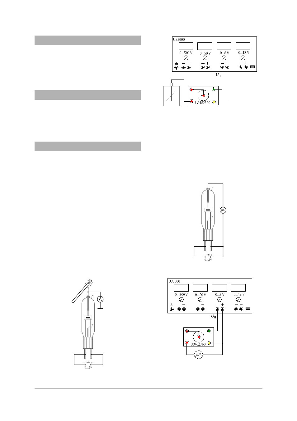
Fig. 1a Circuit set-up for demonstrating the Edison
effect using an electroscope
Fig. 1b
Circuit connection of the 500 V DC power
supply (U33000)
In a second experiment the effect is demonstrated
using a multimeter.
•
Connect the circuit as shown in Fig. 2a/b.
The multimeter shows a current of about 85 µA (the
“Edison current”), as the tungsten filament at a high
temperature emits electrons. Between the negative end
of the heater coil and the anode there is a difference of
+3 V, producing an electric field which accelerates the
electrons so that they reach the anode.
Fig. 2a Circuit set-up for demonstrating the Edison
effect using a multimeter
Fig. 2b
Circuit connection of the 500 V DC power
supply (U33000)