3B Scientific Ultrasonic Echoscope User Manual
Page 5
15
4.2. Determining the frequency of the transducer
in use
From the initial echo of the transducer or from a lightly
damped reflection, it is possible to determine the dis-
tance between two maxima in the high-frequency sig-
nal oscillation with the aid of the zoom function. This
involves placing the measuring cursors at two adjacent
peaks of the high frequency signal as shown in the
above screenshot. The time difference can then be read
directly from the status bar. With this information, the
frequency of the transducer being used may be calcu-
lated (in this case 1/1µs = 1 MHz).
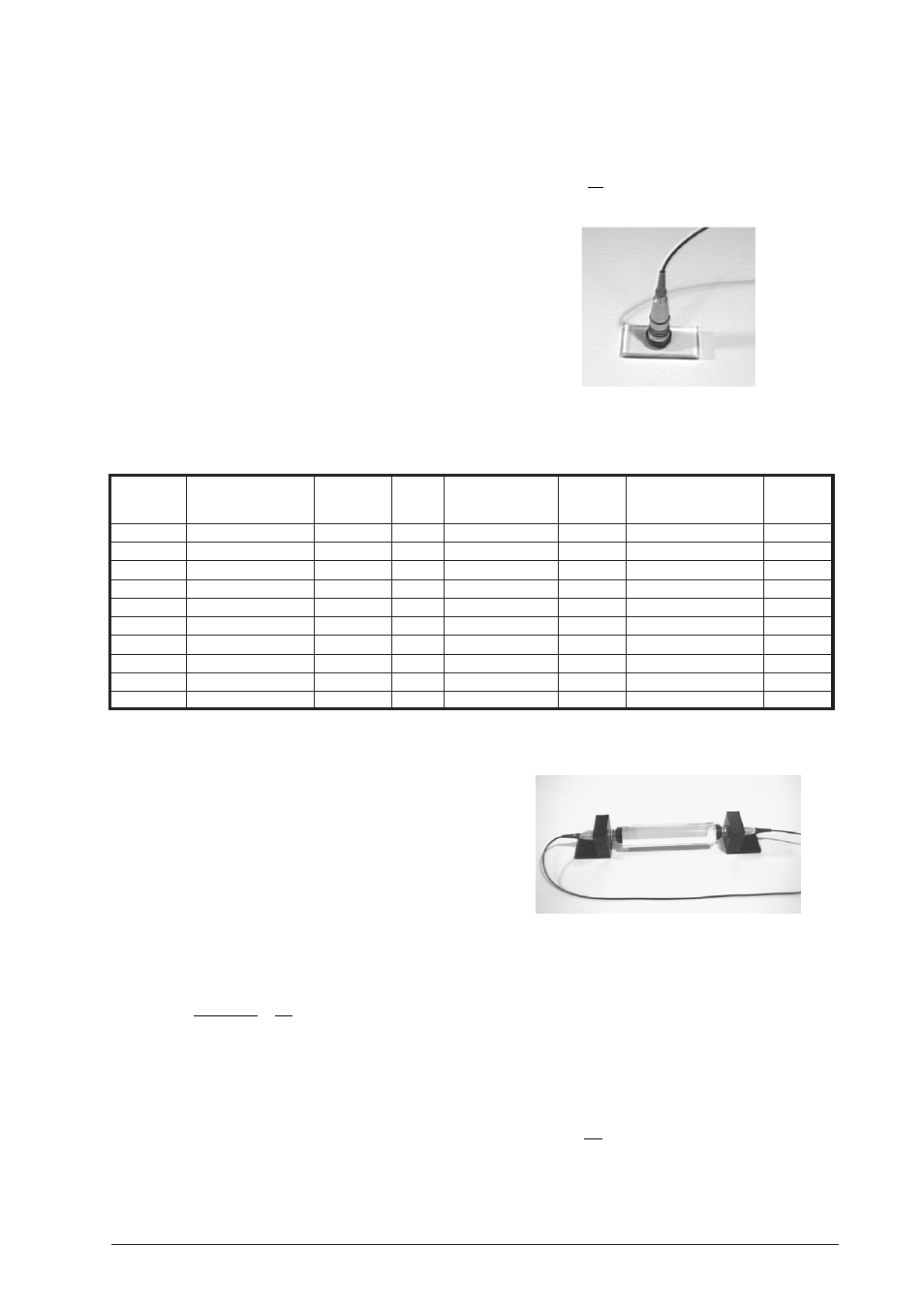
4.3. Longitudinal speed of sound in test bodies
An ultrasonic transducer is attached to test bodies made
of various materials and the time between the emis-
sion of a pulse and the reception of an echo reflected
from a boundary layer is measured (see photograph
below). Knowing the distance s between the transducer
and the edge of the body allows the longitudinal speed
of sound c
L
to be calculated from the measured time t
as follows
c
s
t
L
=
2
(1)
Some results of measurements involving different ma-
terials and geometries are shown in the table below.
Material
Time
∆
t
Distance
∆
s
Speed of sound
∆
c
[µs]
[µs]
[mm]
[mm]
longitudinal [m/s]
[m/s]
Acrylic
Rod 1
84.1
0.4
112.9
0.2
2685
18
Rod 2
112.5
0.6
151.0
0.2
2684
18
Block Length
111.3
0.4
150.0
0.2
2695
13
Width
30.3
0.4
40.2
0.2
2653
48
Height
59.4
0.4
79.8
0.2
2687
25
Standard value
2610-2750
PVC
Block Length
84.9
0.4
98.0
0.2
2309
16
Width
76.8
0.4
87.6
0.2
2281
17
Height
70.3
0.4
80.7
0.2
2296
19
Standard value
2220-2380
4.4. Attenuation of sound in test bodies
Using the measuring cursor for determining amplitude
in the ASH program, the amplitude A of the echo from
the rear surface of two bodies of identical but differ-
ent size can be measured. Applying the law of attenu-
ation to these measurement gives
A = A
0
e
–
α
x
(2)
which can be rearranged to give the sound attenua-
tion coefficient
α
α =
−
(
)
1
2
1
2
2
1
x
x
Ln
A
A
(3)
A
1
is the amplitude for a body of width x
1
and A
2
is that
for a body of width x
2
. The factor of 1/2 in equation (3)
emerges from the fact that sound must traverse the
distance twice when the reflection method is used. If a
transmitter-receiver arrangement is employed, the fac-
tor is omitted.
In all cases care should be taken to ensure that the
amplifier settings are kept identical as far as possible
in order to achieve reproducible results.
Thus the thicknesses of the objects should not differ
greatly. The sound attenuation coefficient in (3) is fre-
quency-dependent so that the frequency used for the
measurement should always be quoted along with the
result. The theoretical frequency-independent absorp-
tion coefficient
α
0
is given by (4) (where
υ
is the fre-
quency of the ultrasonic wave):
α α
ν
=
2
(4)