3B Scientific Stirling Engine G User Manual
Page 2
2
3. Technical data
Motor-generator unit:
max. 12 V DC
2-stage pulley:
30 mm dia., 19 mm dia.
Working piston:
25 mm dia.
Path of working piston:
24 mm
Volumetric change: 24 mm
3
25 mm
12 cm
2
⎛
⎞ ⋅π =
⎜
⎟
⎝
⎠
Minimum volume:
32 cm³
Maximum volume:
44 cm³
Power of the Stirling motor:
1 W approx.
Dimensions: 300x220x160
mm³
approx.
Weight:
1.65 kg approx.
4. Functioning principle
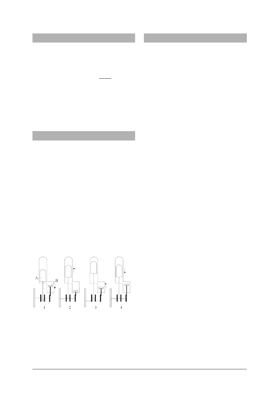
An ideal Stirling cycle has 4 phases (refer to Fig. 1):
Phase 1: Isothermal change of state, during which
the air expands at constant temperature.
Phase 2: Isochoric change of state, during which the
air cools at constant volume in the regene-
rator.
Phase 3: Isothermal change of state, during which
the air is compressed at constant tempera-
ture.
Phase 4: Isochoric change of state, during which the
air in the regenerator is heated back to its
initial temperature.
The process that takes place in the Stirling engine
only approximates to such an ideal cycle because in
fact the four phases overlap. Gas changes from hot to
cold while the expansion is still taking place and not
all the air will yet be in the colder part of the engine
while the compression phase is occurring.
Fig. 1 Functioning principle
(A: Displacement piston, B: Working piston)
5. Operation
5.1 The Stirling Engine as a heat engine
•
Fill the methylated-spirit burner, place it in the
recess in the base-plate, twist out about 1-2 mm
of the wick, and ignite it.
•
Move the displacer piston to its farthest-back
position, and after a short heating-up time
(about 1-2 minutes) push the flywheel gently in
the clockwise direction (as seen from the motor-
generator unit) to set it turning (see Fig. 2).
•
If necessary, adjust the tension of the drive belt
by moving the motor-generator unit.
•
Turn on the filament lamp by moving the switch
to the “up” position.
•
Alternatively, connect an external load through
the 4 mm sockets and drive it by moving the
switch to the “down” position.
Speed without a load:
1000 rpm approx.
Speed with a generator as the load: 650 rpm approx.
Generator voltage:
6 V DC approx.
Pressure difference:
+250 hPa / -150 hPa
5.2 The Stirling motor as a heat pump or refrig-
erator
Additional instruments needed:
DC Power supply 15 V, 1.5 A
U8521121-230
or
DC Power supply 15 V, 1.5 A
U8521121-115
Digital thermometer
U11818
•
Insert temperature sensors into the thermome-
ter sockets and connect them to a measuring in-
strument (see fig. 3).
•
Connect a DC voltage source through the 4 mm
sockets.
•
Adjust the voltage (maximum 12 V) and operate
the Stirling engine with the switch in the “down”
position.
•
Observe the increase or reduction in tempera-
ture.
In the refrigerator mode of operation, the flywheeI
rotates in the clockwise direction (as seen from the
motor-generator unit), whereas in the heat pump
mode it rotates in the anticlockwise direction.
•
To switch between the two modes of operation,
reverse the polarity of the connections.
Pressure difference:
+250 hPa / -150 hPa
Motor voltage:
9 V
Speed:
600 rpm
Temperature difference (with respect to 21° C):
Refrigerator:
-4 K (reservoir: +6 K)
Heat pump:
+13 K (reservoir: -1 K)