3B Scientific Pendulum Rod with Angle Sensor, 12V AC (115V,50__60Hz) User Manual
Page 7
Elwe Didactic GmbH • Steinfelsstr. 6 • 08248 Klingenthal • Germany • www.elwedidactic.com
3B Scientific GmbH • Rudorffweg 8 • 21031 Hamburg • Germany • www.3bscientific.com
Subject to technical amendments
© Copyright 2007 3B Scientific GmbH
5.3 Weighted pendulum
It is possible to investigate oscillations of weighted
pendulums using the set-up shown in Fig. 2.
An x-t (or x-y-t) plotter, a storage oscilloscope or a
computer-based data recording system are all ap-
plicable for recording the results.
For quantitative investigation of the relationship
between the frequency and the length of the pen-
dulum, the relationship
g
l
T
/
2
π
=
is no longer
accurate enough for short pendulum lengths (when
the distance between the fulcrum and the weight
of the pendulum is less than 50 cm).
Precise mathematical treatment requires consi
eration of the moment of inertia of the pendulum
rod, the weight and the pivot mechanism of the
pendulum.
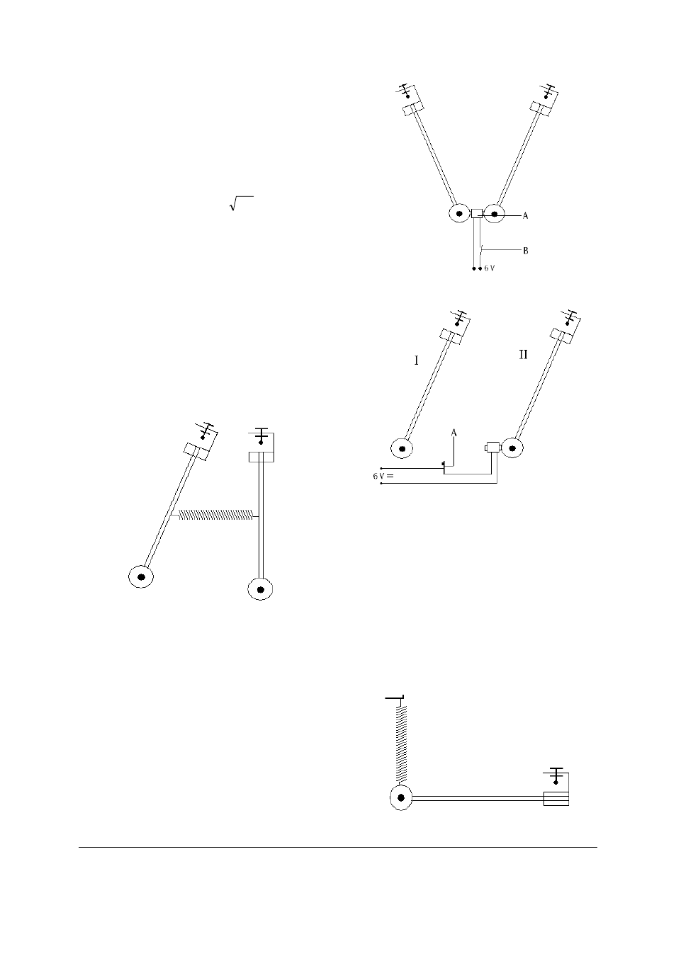
5.4 Coupled weighted pendulums
With two angle sensors investigations can be made
of coupled weighted pendulums (Fig. 5).
The pendulums are linked via a coil spring (Helical
spring 3 N/m
, U15027
) that can be suspended from
the holes in the pendulum rods.
Fig 5
5.6 Lissajous figures
The outputs of the two angle sensors are connected
to the x and y inputs of a coordinate plotter (alte
natively a storage oscilloscope or a computer-based
data recording system). Phase differences between
the two oscillations can be controlled with the aid
of holding magnets and release contacts (Fig. 6, 7).
For the circuit in Fig. 6, pendulum I’s contact plate
is opened at its lowest point. Pendulum II is thus
released with a 90° delay.
Fig 6 A Coil with iron core, B Switch
Fig 7 A Contact plate
If the two pendulums are of differing lengths, Lissa-
jous figures are recorded that are not coincident.
To obtain Lissajous figures with a frequency ratio of
1:2, one of the 1-m pendulum rods must be re-
placed with a 25-cm rod. Fine calibration of the
frequency ratio to precisely 1:2 can be achieved by
carefully adjusting the position of the weight on
the short pendulum rod.
5.6 Spring pendulum
To investigate spring pendulums, the pendulum
rod is secured as in Fig. 8.
Fig. 8