3B Scientific Pendulum Rod with Angle Sensor, 12V AC (115V,50__60Hz) User Manual
Page 6
2
number. If components that are not matched to
each other are used, statistical variations between
individual magnets can require a greater offset
voltage.
The pendulum rod can be fixed either in the direc-
tion of the magnet axis (for a gravity pendulum) or
perpendicular to it (for spring pendulum experi-
ments). In the case of the gravity pendulum the
disc-shaped pendulum bob serves as the weight.
The voltage supply is derived from a 12V AC plug-in
power supply, which is included in the kit.
The
pendulum
U8404275-115 is for operation with
a mains voltage of 115 V (±10%), and U8404275-230
is for operation with a mains voltage of 230 V
(±10%).
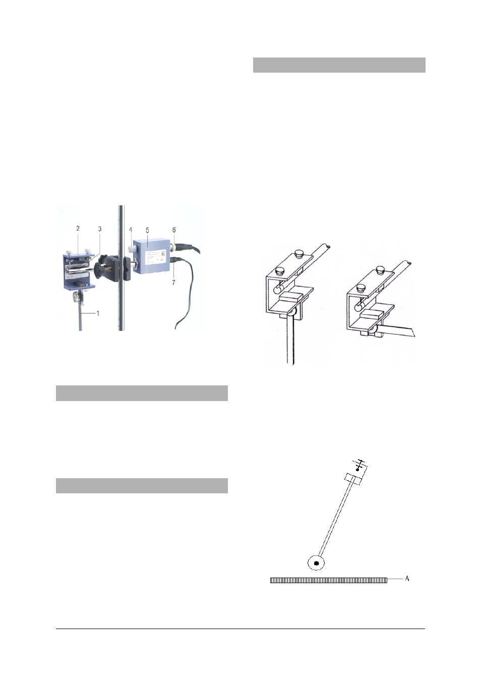
Fig. 1 . Support arrangement for pendulum rod
1 Pendulum rod, 2 Needle bearing, 3 Supporting rod for
angle sensor, 4 Offset adjuster, 5 Angle sensor, 6 BNC
socket, 7 Connecting lead from
plug-in power supply
3. Scope of delivery
1
Pendulum rod
1 Pendulum weight
1
Angle sensor
1
Needle bearing
1 Plug-in power supply
12
V AC
4. Technical data
Operating voltage:
12 V AC
Output voltage:
±
5 V
Output resistance:
500 Ohm
Length of pendulum:
1 m
Pendulum weight:
1 kg
Weight of
angle sensor
:
0.3 kg approx.
Diameter of tube:
10 mm
5. Example experiments
5.1 Instructions for experiment set-up
Depending on how the pendulum rod is mounted
(Fig. 2, 3) the angle sensor can be used for both
weighted and spring pendulums.
In setting a weighted pendulum according to Fig. 2,
make sure the pendulum has a secure base. Ide-
ally, the vertical stand rod should be secured by
means of a table clamp. If necessary, the set-up
may need to be held firm by additional supports.
If the supporting rod for the angle sensor is not
exactly horizontal, the pendulum can be restored
to a vertical position by means of the adjusting
screws.
If the output voltage differs from when the pendu-
lum is in its rest position zero, this can be compen-
sated for by the offset adjuster.
Fig 2
Fig 3
5.2 Determining the output voltage as a func-
tion of the angle of deflection
To evaluate experiments quantitatively it is neces-
sary to know the precise relationship between the
output voltage and the angle of deflection. This can
be determined as in Fig. 4.
Fig 4 A Ruler