3B Scientific Induction Apparatus User Manual
Page 2
2
4. Sample experiments
4.1 General instructions
The following equipment is also needed for the ex-
periments:
1 DC power supply, 1,5 – 15 V
U8521121-115
or
1 DC power supply, 1,5 – 15 V
U8521121-230
1 Measurement amplifier
U8531401-115
or
1 Measurement amplifier
U8531401-230
1 Multimeter ESCOLA10
U8531160
1 HF patch cord, BNC/4 mm plug
U11257
•
Before beginning an experiment, the metal
tracks on the basic instrument, under the frame
with coil and on the plate of magnets, as well as
the brass tube must be rubbed with the fleece to
ensure good electrical contact.
•
Set up the induction apparatus either on top of
an an overhead projector or on a bench.
4.2 Movement of a current-carrying conductor in
a magnetic field
•
Remove the magnet plate from the induction
apparatus.
•
Place the brass tube across the magnet plate so
that the left and right-hand ends of the tube
touch the metal rails.
•
Connect the magnet plate to the mains adaptor,
and feed 1 to 2 A into the sockets.
The brass tube starts to roll over the
magnet plate
by
the Lorentz force acting on the current conducting
electrons in the tube. If the poles of the voltage
source are reversed the direction of the tube's mo-
tion is also reversed.
1 A-2 A
Fig. 1 Motion of a current-carrying conductor in a mag-
netic field
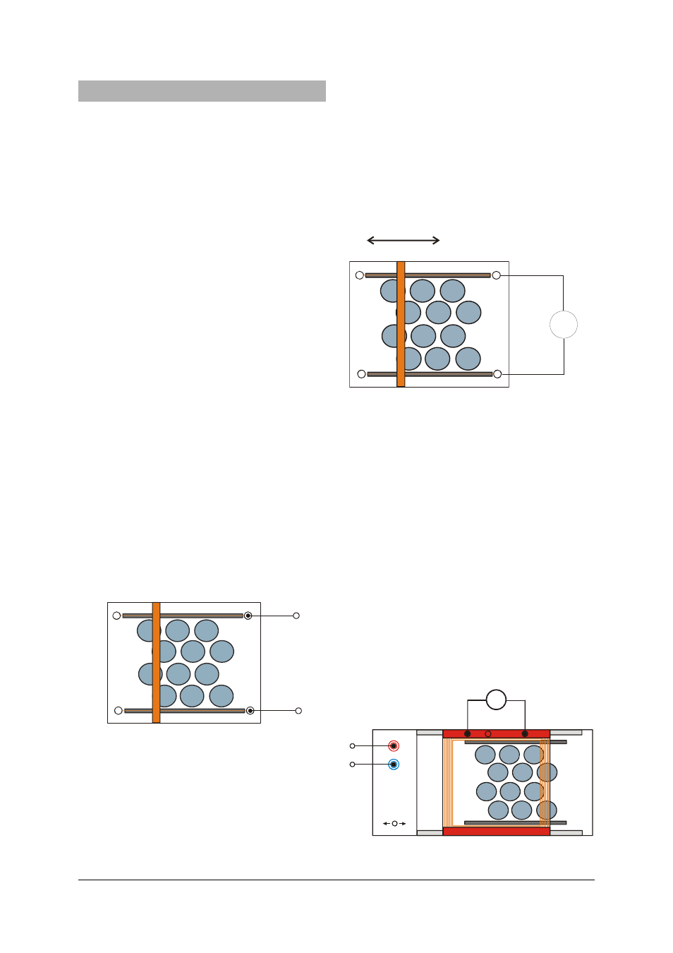
4.3 Electrical induction with a conductor
•
Remove the magnet plate from the induction
apparatus
•
Connect the signal amplifier to the sockets of the
metal tracks and set the measurement range to
100
μV.
•
Place the brass tube across the magnet plate so
that the left and right-hand ends of the pipe
touch the metal rails.
•
While applying a slight downward pressure to
the brass tube, move it at a constant speed
through the magnetic field.
The voltmeter indicates a certain DC voltage. If the
tube's direction is reversed, an voltage of similar
magnitude arises with the opposite polarity. If the
speed is increased, the voltage rises too.
μV
Fig. 2 Electrical induction with a conductor
4.4 Electrical induction with a flat coil
•
Place the frame with coil on the induction appa-
ratus.
•
Connect the induction apparatus to the power
supply.
•
Connect the multimeter to the coil. Set the zero
point at the middle of the scale and select the
100 mV measurement range.
•
Slowly increase the operating voltage until the
conveyor belt slowly moves at a constant speed.
•
Observe the induced voltage.
The voltmeter indicates a DC voltage. If the direction
of the conveyor belt is reversed, a voltage of similar
magnitude arises with the opposite polarity.
If the whole coil is located above the magnetic field,
there is no voltage induced. The coil surface is
smaller than the surface of the magnet plate, thus
the magnetic flux remains constant.
V
mV
Fig. 3 Electrical induction using a flat coil