3B Scientific Heat Pump D (230 V, 60 Hz) User Manual
Page 3
3
ture gradient leads to heat being transferred
from the surroundings into the refrigerant, which
therefore boils and turns into vapour. The quan-
tity of heat Q
a
required for this evaporation is
taken from the surroundings, which cool down as
a result.
3.1.2 Compression
The refrigerant vapour is constantly drawn into
the compressor where it is compressed. This
causes the vapour pressure to rise from p
0
to p.
The boiling point at pressure p is T*. The work W
performed by the compressor raises the tempera-
ture of the vapour to T
h
> T*. T
h
is the temperature
of the refrigerant vapour after it has been thus
raised, i.e. the temperature is above the boiling
point T* corresponding to the pressure p after the
compressor.
3.1.3 Condensing
The compressed vapour is forced into the con-
denser. The temperature of the surroundings
around the condenser is T and is lower than T*. This
means that heat is transferred from the refrigerant
into the environment. This corresponds to the
smaller fraction of Q
z
. The temperature of the va-
pour decreases from T
h
but the vapour does not con-
dense until the condensation temperature T* is
reached. At that point the vapour begins to con-
dense (become liquid) and the heat of condensa-
tion, the greater component of Q
z
, is transferred to
the surroundings, the temperature of which there-
fore rises.
3.1.4 Expansion
The piping connecting the condenser and the
evaporator completes the circuit. The expansion
valve in this pipe allows the pressure difference to
even out. The liquid refrigerant at temperature T* is
allowed to expand so that its pressure decreases
from p in the condenser to p
0
in the evaporator. This
also causes the refrigerant to cool. The lower pres-
sure p
0
results in a lower boiling point T
0
*. There-
fore the expansion also causes the boiling point to
drop so that the temperature T* at which the re-
frigerant leaves the evaporator is now above the
boiling point of the expanded fluid. Part of it there-
fore starts to evaporate. The heat of evaporation re-
quired for this is provided by the cooling of the re-
frigerant itself until pressure and temperature reach
p
0
and T
0
* and the refrigerant returns to its initial
state thus completing the cycle.
The heat energy required to evaporate the refrigerant
per unit time in the evaporator can be supplied either
by the extensive cooling of a small volume of air or by
lesser cooling of a large volume of air. The energy
associated with a material is dependent on its tem-
perature and its quantity. In practice the cooling of
the medium around the evaporator, such as the cool-
ing of air outdoors, only corresponds to a few degrees.
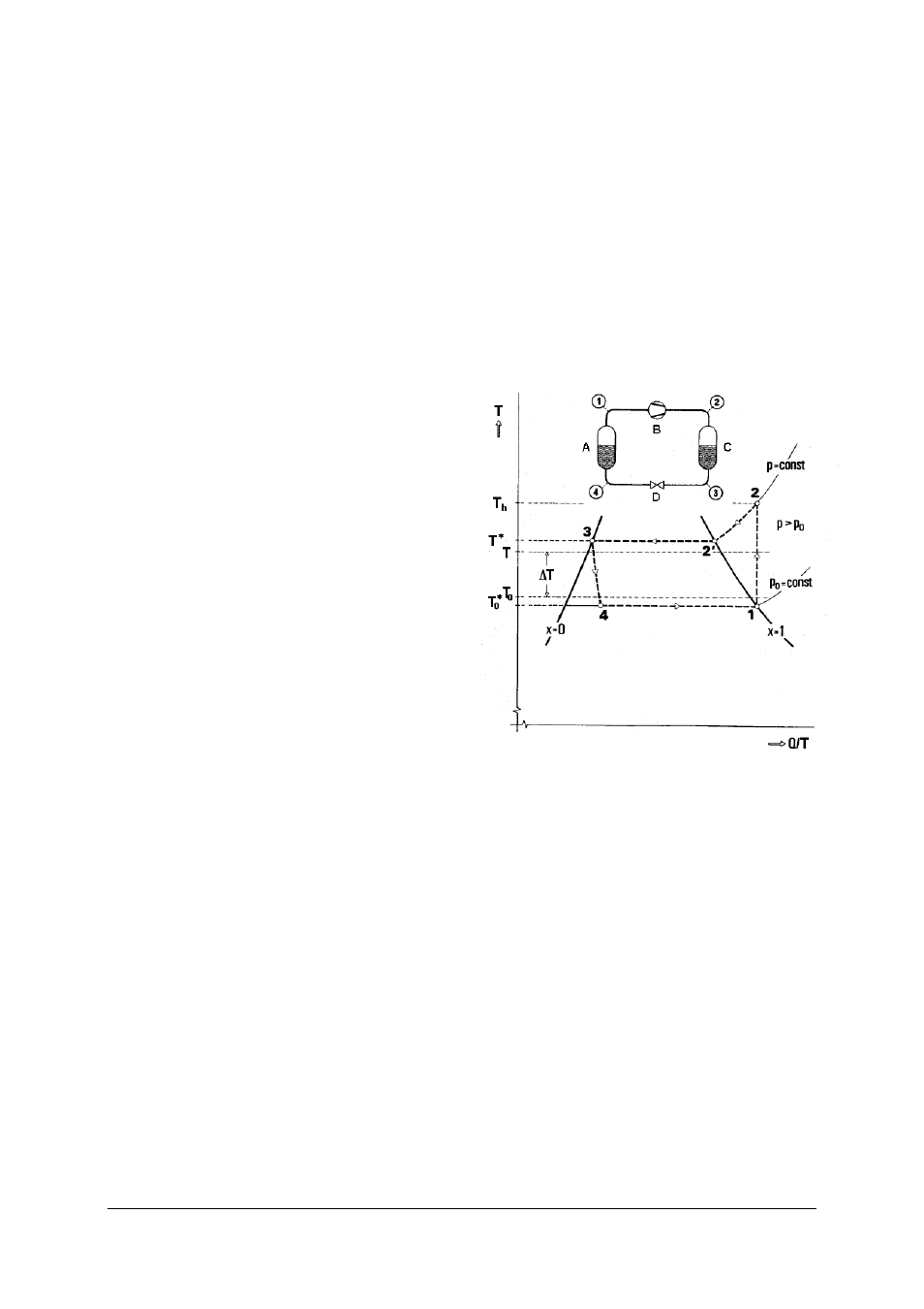
3.2 The processes in the circuit as a T, Q/T diagram
The heat pump cycle is often represented in a state
diagram with the «Temperature» T as its ordinate and
the quotient «Heat divided by absolute temperature»
Q/T, which is called entropy, as the abscissa (Fig. 2).
The value x in this diagram represents the ratio of
refrigerant vapour to liquid. When x = 0 and anywhere
to the left of this line (left-hand limit), all the refrigerant
is liquid. To the right of the line an increasing quantity
of the refrigerant is gaseous until a line with x = 1
(right-hand limit) is reached, after which the refriger-
ant is entirely vapour. The sequence of processes in
the cycle already described will now be explained
again in terms of this diagram:
Fig. 2 The process in a heat pump cycle as a T, Q/T diagram
A Evaporator, B Compressor, C Condenser, D Expansion
valve
Gaseous refrigerant at a pressure p
0
and temperature
T
0
* (state 1) is sucked into the compressor and com-
pressed. The amount of work done in this case is W.
This is converted into heat and transferred to the
refrigerant. The pressure p
0
increases to p. The higher
pressure p corresponds to a higher boiling point T*.
Temperature rises from T
0
* to T
h
(state 2).
The compressed refrigerant flows into the condenser.
The temperature of the condenser's surroundings T is
lower than T*. By emitting heat, the vapour cools
from T
h
down to the condensation temperature, the
boiling point T* corresponding to the pressure p (state
2'). It then condenses by emitting its heat of conden-
sation (Q
z
).
Now that the refrigerant is liquid at temperature T*
and pressure p (state 3) it is allowed to flow to the
evaporator via an expansion valve. During the course
of this, the pressure drops back to p
0
, and the drop in
pressure causes the temperature to fall to T
0
* (state 4).