3B Scientific Heat Pump D (230 V, 60 Hz) User Manual
Page 2
2
Button Function
Zeit (Time)
displays the time / operating time of
the compresor (ED)
(changes when you press the button)
Strom (Cur-
rent)
displays the current consumption of
the compresor
Spannung
(Voltage)
displays the mains voltage
Leistung
(Power)
displays the momentary power con-
sumption
Energie
(Energy)
displays the energy, (unit: Wh)
Zeit (Time)
> 6s
Reset function for time, ED and
energy
The evaporator and condenser are constructed as
coils of copper piping and each is immersed in a
beaker filled with 2000 ml of water that serves as a
reservoir of heat in order to determine the quantity
of energy absorbed or emitted. Two additional ther-
mometers are required in order to measure the
temperature of the water in the beakers.
Two large manometers display the pressure of the
refrigerant in both heat exchangers. An overpressure
cut-out switch disconnects the heat pump from the
mains if the excess pressure reaches 15 bars.
So that the properties of the refrigerant in liquid and
gaseous states and the processes of conversion can
be viewed, the heat pump is equipped with viewing
windows. These allow the interior of the pump to be
seen and the state of the refrigerant to be observed
immediately after the evaporator or condenser.
The heat pump is available for two different mains
volatages. U8440600-230 is designed for 230 V (±10
%), 50 Hz mains supplies, while the U8440600-115
model is for 115 V (±10 %), 60 Hz supplies.
3. Technical data
Compressor power:
120 W, power consump
tion dependent on operat-
ing
state
Evaporator temperature: -10° C
Refrigerant (CFC-free):
R 134A (Tetrafluorethan, C
2
H
2
F
4
)
Boiling point:
-26° C
Manometer:
160 mm dia., evaporator
(suction intake) up to 9
bars; condenser (pressure
pipe) up to 24 bars
Overpressure cut-off:
disconnects compressor
from the mains at 15 bars
Power supply:
115 V, 60 Hz or 230 V, 50 Hz
Dimensions:
750 x 350 x 540 mm
3
Weight:
21 kg approx.
4. Operating principle
3.1 The processes in a heat pump circuit
In the most important and widely used type of heat
pump, the compressor heat pump, a substance in
the form of a liquid with a low boiling point circu-
lates in a closed loop. It passes through four differ-
ent processes. It is evaporated, compressed, con-
densed and then allowed to expand (see Fig. 1).
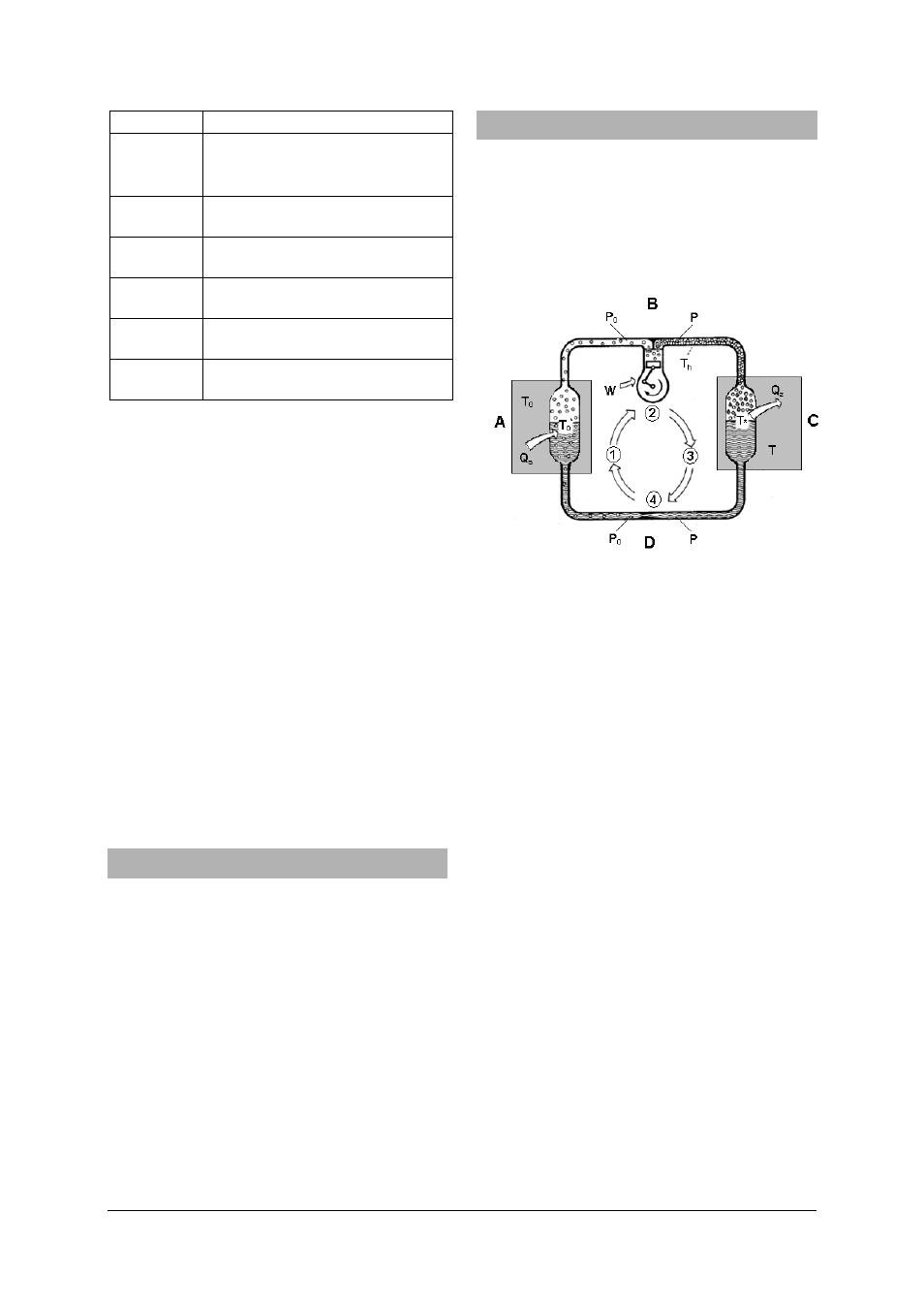
Fig. 1 Circulation in a heat pump
A Evaporator
B Compressor
C Condenser
D Expansion
valve
P
0
Low pressure in the evaporator segment from
the outlet of the expansion valve to the input
of the compressor
p
High pressure in the condenser segment from
the outlet of the compressor to the input of
the expansion valve
T
0
Temperature of the medium (soil, water, air)
surrounding the evaporator from which a
quantity of heat Q
a
is absorbed
T
Temperature of the medium (usually centrally
heated water), surrounding the condenser
which absorbs a quantity of heat Q
z
T
0
*
Boiling point of the refrigerant in the evapo-
rator
at
pressure
p
0
T
h
Temperature of the refrigerant vapour
after
compression
T*
Boiling point of the refrigerant in the con-
denser at pressure p
Q
a
Heat absorbed by the evaporator
Q
Z
Heat emitted by the condenser
W
Work performed by the compressor
3.1.1 Evaporation
In the evaporator the liquid refrigerant experi-
ences a low pressure p
0
. The temperature T
0
in
the medium surrounding the evaporator is higher
than the boiling point of the refrigerant T
0
* cor-
responding to the pressure p
0
. This tempera-