Prokit's Industries MT-3102 User Manual
Page 2
3 1/2 2A Mini Digital Clamp Meter
user manual
2
SAFETY WARNING
1.
Read the operating instructions before using the
instrument and pay particular attention to all
WARNINGS and CAUTIONS in this instruction
manual.
2.
Be sure that the cover and the test leads of the
meter are in good conditions.
3.
Set the range / function switch at the correct position
when measuring.
4.
Make sure to insert the red and the black test leads
to their appropriate jacks. The black test lead should
be connected first when measuring while the red
test lead should be disconnected first after
measuring.
5.
When the range and function changes, both test
leads should be disconnected.
6.
To avoid damage to the instrument, never exceed
the allowable maximum input of each range.
7.
Be care of electric shock hazard when the voltage to
be tested is above DC 60V or AC 30V.
8.
To avoid electric shock, do not open the battery
compartment cover when making measurement.
9.
Remove the test leads from the circuit being
measured before replacing the battery.
10. Do not change the built-in circuit to avoid damage to
the meter.
11. Do not use or store the instrument in an explosive
atmosphere (i.e. the presence of flammable gas or
fume, vapor or dust)
12. CAT II-Measurement Category II is for
measurements performed on circuits directly
connected to low voltage installation.(Examples are
measurements on household appliances, portable
tools and similar equipments.)Dot not use the meter
3 1/2 2A Mini Digital Clamp Meter
user manual
3
for measurements within Measurement Categories
III and IV
13.
MT-3102 SELECT
MAX
HOLD
DC Voltage
N/A
●
●
AC Voltage
N/A
●
●
Resistance,
Continuity,Diode test
● N/A ●
Temperature
℃
/℉(K-Type)
● N/A ●
DC current 2/20A
N/A
●
●
AC current 200/400A
N/A
●
●
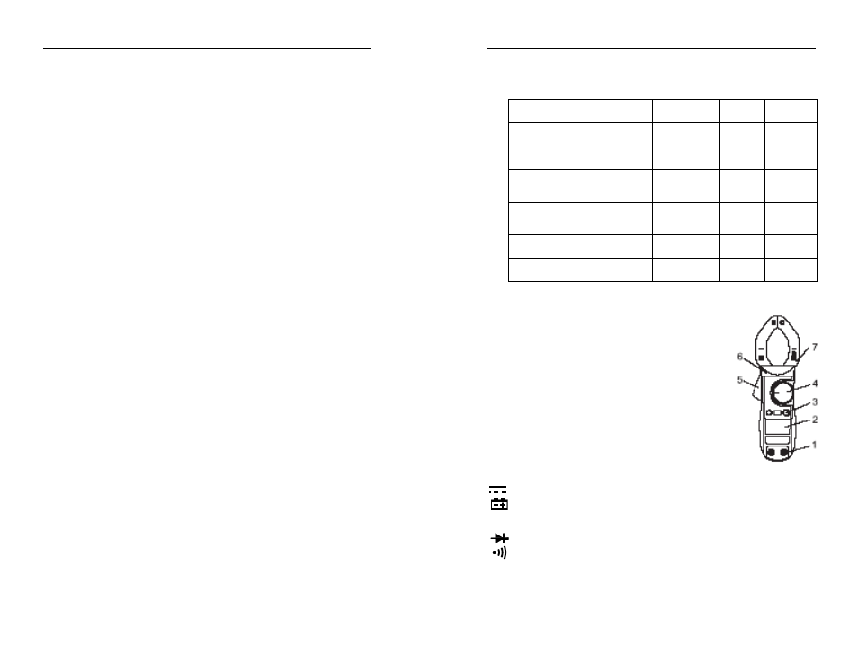
FRONT PANEL DESCRIPTION
1. COM Input Jack / V/Ω Input Jack
2. 1/2-digit LCD Display Panel
3. Function Switch Button
(SEL/MAX/HOLD)
4. Function/range select rotary selector
5. Trigger
6. Protection edge
7. Current Clamp
LCD DISPLAY SYMBOLS
~
AUTO
HOLD
℃
/℉
Alternating signal test
Direct signal test
Low Battery
Auto range mode ?
Diode test
Continuity buzzer
This indicates that the display data is being held
Temperature test