Detailed description – Rainbow Electronics MAX6983 User Manual
Page 7
MAX6983
16-Port, 36V Constant-Current LED Driver with
LED Fault Detection and Watchdog
_______________________________________________________________________________________
7
Detailed Description
The MAX6983 LED driver comprises a 4-wire serial
interface driving eight constant-current sinking open-
drain output ports. The outputs drive LEDs in either sta-
tic or multiplex applications (Figure 1). The constant-
current outputs are guaranteed for current accuracy
not only with chip-supply voltage variations (5V ±10%
and 3V to 5.5V), but also over a realistic range of driver
output voltage drop (0.8V to 2.5V). The drivers use cur-
rent-sensing feedback circuitry (not simple current mir-
rors) to ensure very small current variations over the full
allowed range of output voltage (see the Typical
Operating Characteristics).
The 4-wire serial interface comprises a 16-bit shift reg-
ister and a 16-bit transparent latch. The shift register is
written through a clock input CLK and a data input DIN
and the data propagates to a data output DOUT. The
data output allows multiple drivers to be cascaded and
operated together. The contents of the 16-bit shift reg-
ister are loaded into the transparent latch through a
latch-enable input LE. The latch is transparent to the
shift register outputs when high, and latches the cur-
rent state on the falling edge of LE.
Each driver output is an open-drain, constant-current
sink that should be connected to the cathode of either
a single LED or a series string of multiple LEDs. The
LED anode can be connected to a supply voltage of up
to 36V, independent of the MAX6983 supply, V+. The
constant-current capability is up to 55mA per output,
set for all 16 outputs by an external resistor, R
SET
.
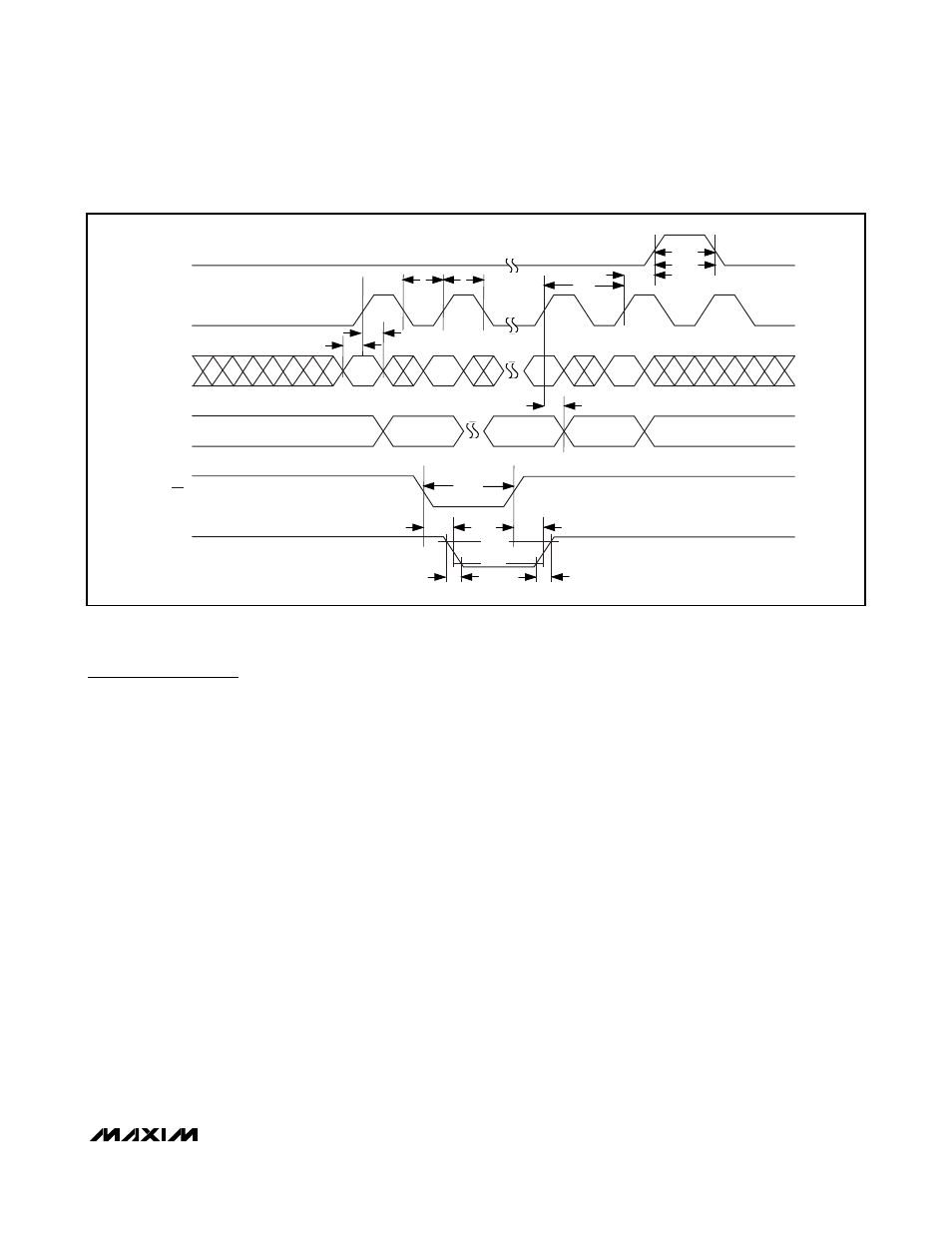
4-Wire Serial Interface
The serial interface on the MAX6983 is a 4-wire serial
interface using four inputs (DIN, CLK, LE, and OE) and
a data output (DOUT). This interface is used to write
display data to the MAX6983. The serial-interface data
word length is 16 bits, D0–D15. See Figure 2.
The functions of the five interface pins are as follows.
DIN is the serial-data input, and must be stable when it
is sampled on the rising edge of CLK. Data is shifted
in, MSB first. This means that data bit D15 is clocked in
first, followed by 15 more data bits, finishing with the
LSB D0.
CLK is the serial-clock input, which shifts data at DIN
into the MAX6983 16-bit shift register on its rising edge.
LE is the latch load input of the MAX6983, which trans-
fers data from the MAX6983 16-bit shift register to its 16-
bit latch when LE is high (transparent latch), and latches
the data on the falling edge of LE (Figure 2).
Figure 2. 4-Wire Serial-Interface Timing Diagram
.
D15
D14
t
DS
t
DH
t
CL
t
CP
t
DO
t
OEW
t
OEL
t
f
t
r
t
OEH
t
LS
t
LW
t
CH
D1
D0
D15
LE
CLK
DIN
DOUT
OE
OUT_
80%
20%
t
LF