Typical operating characteristics, 3v timing characteristics – Rainbow Electronics MAX6983 User Manual
Page 4
MAX6983
16-Port, 36V Constant-Current LED Driver with
LED Fault Detection and Watchdog
4
_______________________________________________________________________________________
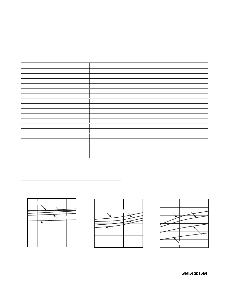
SUPPLY CURRENT vs. SUPPLY VOLTAGE
(INTERFACE IDLE, ALL OUTPUTS OFF, R
SET
= 720
Ω)
MAX6983 toc01
SUPPLY VOLTAGE (V)
SUPPLY CURRENT (mA)
5.0
4.5
4.0
3.5
1.85
1.90
1.95
2.00
1.80
3.0
5.5
T
A
= +125
°C
T
A
= +85
°C
T
A
= -40
°C
T
A
= +25
°C
SUPPLY CURRENT vs. SUPPLY VOLTAGE
(INTERFACE IDLE, ALL OUTPUTS OFF, R
SET
= 360
Ω)
MAX6983 toc02
SUPPLY VOLTAGE (V)
SUPPLY CURRENT (mA)
5.0
4.5
4.0
3.5
3.55
3.60
3.65
3.70
3.50
3.0
5.5
T
A
= +125
°C
T
A
= +85
°C
T
A
=-40
°C
T
A
= +25
°C
SUPPLY CURRENT vs. SUPPLY VOLTAGE
(INTERFACE IDLE, ALL OUTPUTS ON, R
SET
= 720
Ω)
MAX6983 toc03
SUPPLY VOLTAGE (V)
SUPPLY CURRENT (mA)
5.0
4.5
4.0
3.5
20
25
30
35
40
45
T
A
= +125
°C
T
A
= +85
°C
T
A
= -40
°C
T
A
= +25
°C
15
3.0
5.5
Typical Operating Characteristics
(T
A
= +25°C, unless otherwise noted.)
3.3V TIMING CHARACTERISTICS
(Typical Operating Circuit, V+ = 3V to 5.5V, T
A
= T
MIN
to T
MAX
, unless otherwise noted.) (Notes 1, 2)
PARAMETER
SYMBOL
CONDITIONS
MIN
TYP
MAX
UNITS
CLK_ Clock Period
t
CP
52
ns
CLK_ Pulse-Width High
t
CH
24
ns
CLK_ Pulse-Width Low
t
CL
24
ns
DIN_ Setup Time
t
DS
4
ns
DIN_ Hold Time
t
DH
8
ns
DOUT_ Propagation Delay
t
DO
12
50
ns
DOUT_ Rise and Fall Time
C
DOUT
= 10pF, 20% to 80%
12
ns
LE Setup Time
t
LS
15
ns
LE Rising to OUT_ Rising Delay
(Note 3)
120
ns
LE Rising to OUT_ Falling Delay
(Note 3)
310
ns
C LK_ Ri si ng to OU T_ Ri si ng D el ay
(Note 3)
120
ns
C LK_ Ri si ng to OU T_ Fal l i ng D el ay
(Note 3)
330
ns
OE_ Rising to OUT_ Rising Delay
t
OEH
(Note 3)
120
ns
OE_ Falling to OUT_ Falling Delay
t
OEL
(Note 3)
330
ns
LED Output OUT_ Turn-On Fall
Time
t
f
80% to 20% (Note 3)
120
ns
LED Output OUT_ Turn-Off Rise
Time
t
r
20% to 80% (Note 3)
120
ns
Note 1: All parameters tested at T
A
= +25°C. Specifications over temperature are guaranteed by design.
Note 2: See Figure 3.
Note 3: A 65
Ω pullup resistor is connected from OUT_ to 5.5V.