Rainbow Electronics MAX934 User Manual
Page 10
MAX931-MAX934
maximum difference between REF and HYST (50mV)
will therefore produce a 100mV max hysteresis band.
Use the following equations to determine R1 and R2:
Where I
REF
(the current sourced by the reference)
should not exceed the REF source capability, and
should be significantly larger than the HYST input
current. I
REF
values between 0.1µA and 4µA are
usually appropriate. If 2.4M
Ω
is chosen for
R2 (I
REF
= 0.5µA), the equation for R1 and V
HB
can be
approximated as:
When hysteresis is obtained in this manner for
the MAX932/MAX933, the same hysteresis applies to
both comparators.
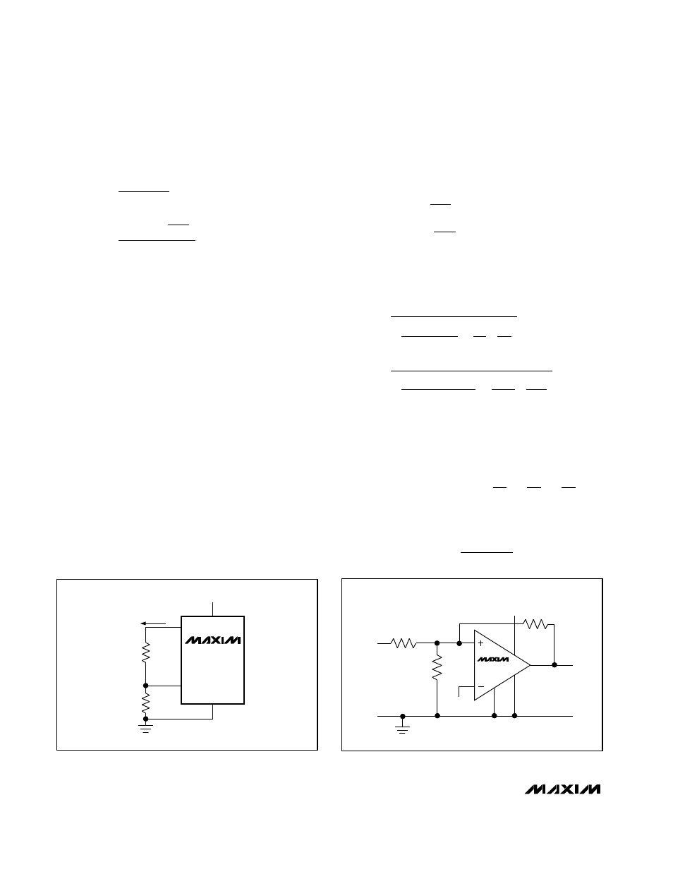
Hysteresis (MAX934)
Hysteresis can be set with two resistors using positive
feedback, as shown in Figure 4. This circuit generally
draws more current than the circuits using the HYST
pin on the MAX931/MAX932/MAX933, and the high
feedback impedance slows hysteresis. The design
procedure is as follows:
1. Choose R3. The leakage current of IN+ is under 1nA
(up to +85°C), so the current through R3 can be
around 100nA and still maintain good accuracy.
The current through R3 at the trip point is V
REF
/R3,
or 100nA for R3 = 11.8M
Ω
. 10M
Ω
is a good
practical value.
2. Choose the hysteresis voltage (V
HB
), the voltage
between the upper and lower thresholds. In this
example, choose V
HB
= 50mV.
3. Calculate R1.
4. Choose the threshold voltage for V
IN
rising (V
THR
). In
this example, choose V
THR
= 3V.
5. Calculate R2.
A 1% preferred value is 64.9k
Ω
.
6. Verify the threshold voltages with these formulas:
V rising :
V
V
R1
1
R1
1
R2
1
R3
V falling :
V
V
R1
V
R3
IN
THR
REF
IN
THF
THR
=
Ч
Ч
+
+
=
−
Ч
+
(
)
R2 =
V
(V
1
R1
1
R3
3
(1.182 100k)
1
100k
1
10M
65.44k
THR
REF R1)
1
1
Ч
−
−
=
Ч
−
−
=
Ω
R1 = R3
V
V
10M
0.05
5
100k
HB
Ч
+
=
Ч
=
Ω
R1 (k ) = V
(mV)
HB
Ω
R1 =
V
2
I
R2 =
1.182 –
V
2
I
HB
REF
HB
REF
×
(
)
Ultra Low-Power, Low-Cost
Comparators with 2% Reference
10
______________________________________________________________________________________
GND
V-
V+
MAX934
OUT
R3
R1
R2
V
REF
V
IN
V+
Figure 4. External Hysteresis
7
2
5
6
HYST
REF
V-
V+
R1
R2
MAX931
MAX932
MAX933
2.5V TO 11V
I
REF
Figure 3. Programming the HYST Pin