Pin configuration chip information – Rainbow Electronics MAX1449 User Manual
Page 16
MAX1449
10-Bit, 105Msps, Single +3.3V, Low-Power
ADC with Internal Reference
16
______________________________________________________________________________________
Total Harmonic Distortion (THD)
THD is typically the ratio of the RMS sum of the first five
harmonics of the input signal to the fundamental itself.
This is expressed as:
where V
1
is the fundamental amplitude, and V
2
through
V
5
are the amplitudes of the 2nd- through 5th-order
harmonics.
Spurious-Free Dynamic Range (SFDR)
SFDR is the ratio expressed in decibels of the RMS
amplitude of the fundamental (maximum signal compo-
nent) to the RMS value of the next largest spurious
component, excluding DC offset.
Intermodulation Distortion (IMD)
The two-tone IMD is the ratio expressed in decibels of
either input tone to the worst 3rd-order (or higher) inter-
modulation products. The individual input tone levels
are at -6.5dB full scale and their envelope is at -0.5dB
full scale.
THD
V
V
V
V
V
=
×
+
+
+
20
2
2
3
2
4
2
5
2
1
log
(
)
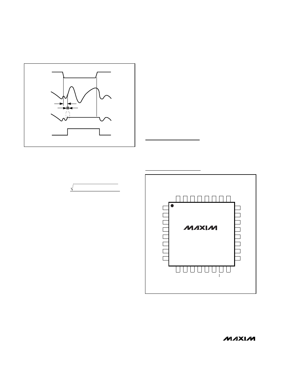
HOLD
ANALOG
INPUT
SAMPLED
DATA (T/H)
T/H
t
AD
t
AJ
TRACK
TRACK
CLK
Figure 10. T/H Aperture Timing
Pin Configuration
Chip Information
TRANSISTOR COUNT: 5684
PROCESS: CMOS
MAX1449
TQFP
TOP VIEW
32
28
29
30
31
25
26
27
REFIN
GND
REFOUT
D0
REFP
D1
D2
D3
10
13
15
14
16
11
12
9
V
DD
GND
V
DD
PD
CLK
OE
GND
D9
17
18
19
20
21
22
23
OGND
24
D4
T.P.
OV
DD
D5
D6
D7
D8
2
3
4
5
6
7
8
GND
IN-
IN+
GND
GND
V
DD
COM
1
REFN