Detailed description, Control scheme – Rainbow Electronics MAX1606 User Manual
Page 7
MAX1606
28V Internal Switch LCD Bias Supply
with True Shutdown
_______________________________________________________________________________________
7
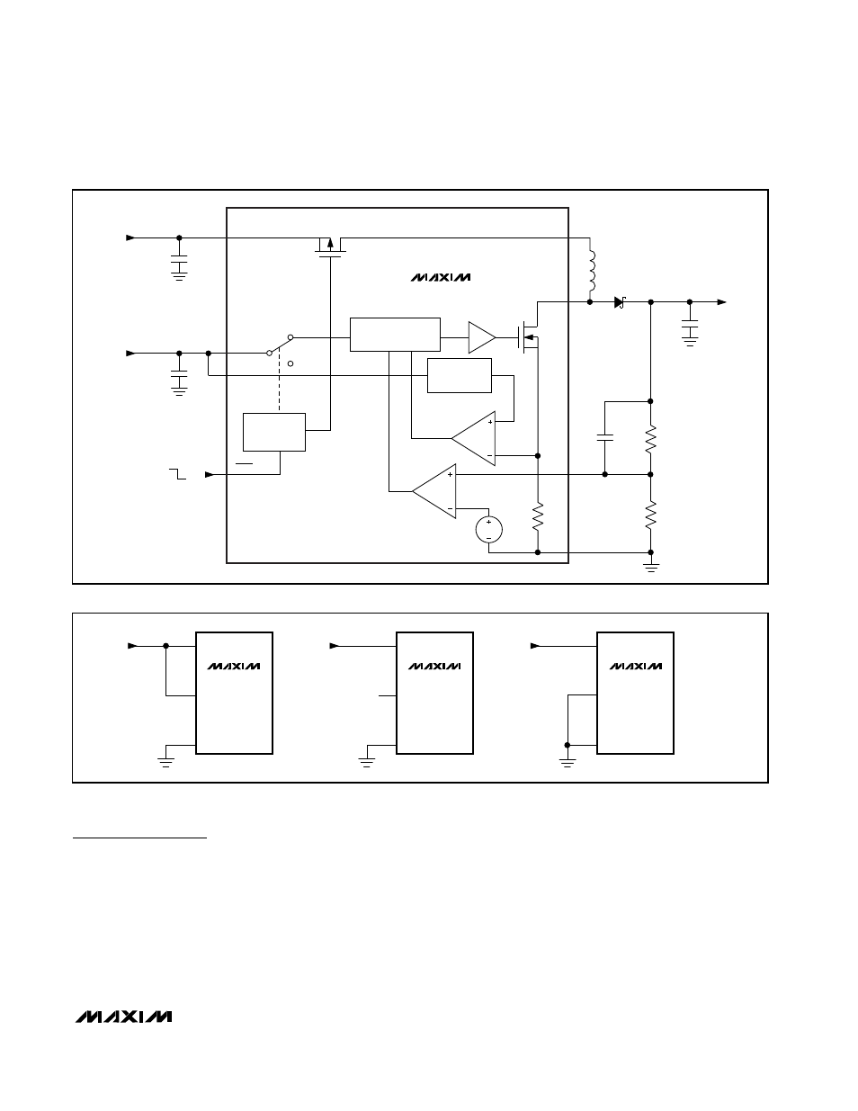
Detailed Description
The MAX1606 step-up DC-DC converter operates from a
2.4V to 5.5V supply and converts voltages as low as
0.8V up to 28V. The device includes an internal switch-
ing MOSFET with a 0.8
Ω on-resistance and selectable
current limit (Figure 1) and consumes 160µA of supply
current. During startup, the MAX1606 extends the mini-
mum off-time, limiting initial battery surge current. The
MAX1606 uses a P-channel MOSFET to isolate the out-
put from the input during true shutdown mode. This isola-
tion switch also includes short-circuit current limiting,
which protects the inductor and diode during a short-cir-
cuit fault.
Control Scheme
The MAX1606 features a minimum off-time, current-limit-
ed control scheme. The duty cycle is governed by a pair
of one-shots that set a minimum off-time and a maximum
on-time. The switching frequency can be up to 500kHz
and depends upon the load and input voltage. The peak
current limit of the internal N-channel MOSFET is pin
selectable and may be set at 125mA, 250mA, or 500mA
(Figure 2).
N
ON
OFF
SHDN
V
IN
= 0.8V TO 5.5V
BATT
V
CC
LIM
SHUTDOWN
LOGIC
1.25V
FB
LX
D1
R1
R2
SW
L1
10
µH
LOGIC
CONTROL
V
CC
= 2.4V TO 5.5V
C1
C2
V
OUT
= V
IN
TO 28V
C
OUT
C
FF
MAX1606
CURRENT
LIMIT
ERROR
AMPLIFIER
I
LIM
Figure 1. Functional Diagram
Figure 2. Setting the Peak Inductor Current Limit
GND
LIM
GND
V
CC
V
CC
LIM
GND
V
CC
LIM
NO CONNECTION
V
CC
(2.4V TO 5.5V)
V
CC
(2.4V TO 5.5V)
V
CC
(2.4V TO 5.5V)
IPEAK = 500mA
IPEAK = 250mA
IPEAK = 125mA
MAX1606
MAX1606
MAX1606