Rainbow Electronics MAX1837 User Manual
Page 8
MAX1836/MAX1837
24V Internal Switch, 100% Duty Cycle,
Step-Down Converters
8
_______________________________________________________________________________________
stant-frequency pulse-width-modulation (PWM) con-
trollers that switch the MOSFET unnecessarily.
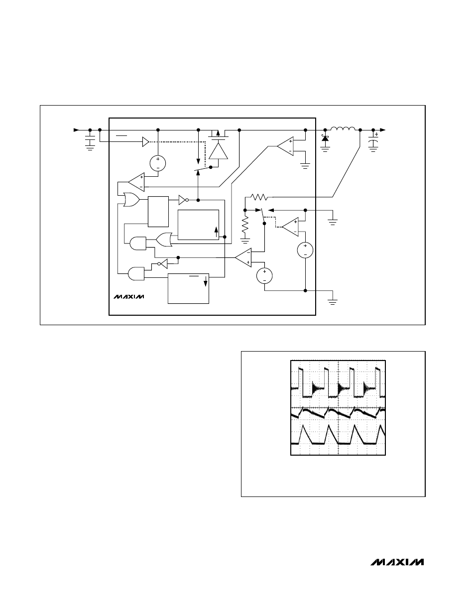
When the output voltage is too low, an error comparator
sets a flip-flop, which turns on the internal P-channel
MOSFET and begins a switching cycle (Figure 3). As
shown in Figure 4, the inductor current ramps up linear-
ly, charging the output capacitor and servicing the
load. The MOSFET turns off when the current limit is
reached, or when the maximum on-time is exceeded
while the output voltage is in regulation. Otherwise, the
MOSFET remains on, allowing a duty cycle up to 100%
to ensure the lowest possible dropout voltage. Once
the MOSFET turns off, the flip-flop resets, diode D1
turns on, and the current through the inductor ramps
back down, transferring the stored energy to the output
capacitor and load. The MOSFET remains off until the
0.5µs minimum off-time expires and the inductor cur-
rent ramps down to zero, and the output voltage drops
back below the set point.
4
µs/div
CIRCUIT OF FIGURE 2, V
IN
= 12V
A. V
LX
, 5V/div
B. V
OUT
= 3.3V, 20mV/div, 200mA LOAD
C. INDUCTOR CURRENT, 500mA/div
10V
0
500mA
3.3V
A
B
C
0
Figure 4. Discontinuous-Conduction Operation
INPUT
4.5V OR 24V
C
IN
OUTPUT
3.3V OR 5V
D1
L1
C
OUT
MAX1836
MAX1837
IN
GND
LX
SHDN
FB
OUT
Q
MAXIMUM
ON-TIME
DELAY
TRIG
Q
MAXIMUM
OFF-TIME
DELAY
TRIG
Q
R
S
V
SENSE
V
SET
1.25V
100mV
Figure 3. Functional Diagram