Detailed description, Pin description, Current-limited control architecture – Rainbow Electronics MAX1837 User Manual
Page 7
MAX1836/MAX1837
24V Internal Switch, 100% Duty Cycle,
Step-Down Converters
_______________________________________________________________________________________
7
Detailed Description
The MAX1836/MAX1837 step-down converters are
designed primarily for battery-powered devices, note-
book computers, and industrial control applications. A
unique current-limited control scheme provides high
efficiency over a wide load range. Operation up to
100% duty cycle allows the lowest possible dropout
voltage, increasing the useable supply voltage range.
Under no-load, the MAX1836/MAX1837 draw only
12µA, and in shutdown mode, they draw only 3µA to
further reduce power consumption and extend battery
life. Additionally, an internal 24V switching MOSFET,
internal current sensing, and a high switching frequen-
cy minimize PC board space and component cost.
Current-Limited Control Architecture
The MAX1836/MAX1837 use a proprietary current-limit-
ed control scheme that operates with duty cycles up to
100%. These DC-DC converters pulse as needed to
maintain regulation, resulting in a variable switching fre-
quency that increases with the load. This eliminates the
high supply currents associated with conventional con-
PIN
NAME
FUNCTION
1
FB
Dual-Mode Feedback Input. Connect to GND for the preset 3.3V (MAX183_EUT33) or 5.0V (MAX183_EUT50)
output. Connect to a resistive divider between the output and FB to adjust the output voltage between 1.25V
and V
IN
, and connect the OUT pin to GND. When setting output voltages above 5.5V, permanently connect
SHDN to IN.
2
GND
Ground
3
IN
Input Voltage. 4.5V to 24V input range. Connected to the internal P-channel power MOSFET’s source.
4
LX
Inductor Connection. Connected to the internal P-channel power MOSFET’s drain.
5
SHDN
Shutdown Input. A logic low shuts down the MAX1836/MAX1837 and reduces supply current to 3
µA. LX is
high impedance in shutdown. Connect to IN for normal operation. When setting output voltages above 5.5V,
permanently connect SHDN to IN.
6
OUT
Regulated Output Voltage High-Impedance Sense Input. Internally connected to a resistive divider. Connect
to the output when using the preset output voltage. Connect to GND when using an external resistive divider
to adjust the output voltage.
Pin Description
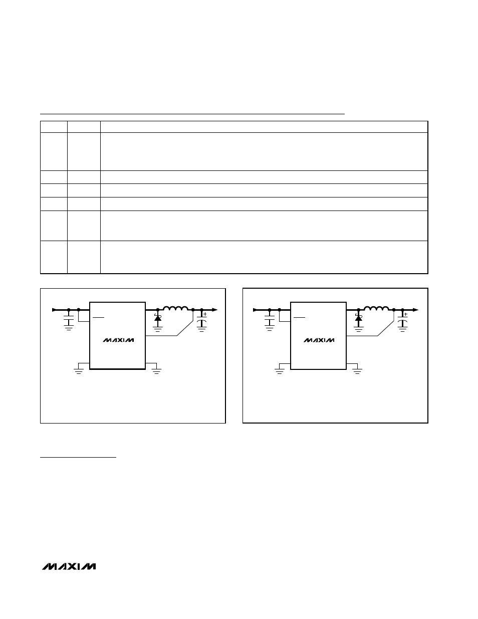
MAX1836
IN
GND
LX
FB
OUT
OUTPUT
3.3V OR 5V
INPUT
4.5V OR 12V
C
IN
10
µF
25V
D1
L1
47
µH
C
OUT
100
µF
6.3V
C
IN
= TAIYO YUDEN TMK432BJ106KM
L1 = SUMIDA CDRH5D28-470
C
OUT
= SANYO POSCAP 6TPC100M (SMALLER CAPACITORS CAN BE USED FOR 5V)
D1 = NIHON EP05Q03L
NOTE: HIGH-CURRENT PATHS SHOWN WITH BOLD LINES.
SHDN
Figure 1. Typical MAX1836 Application Circuit
MAX1837
IN
GND
LX
SHDN
FB
OUT
OUTPUT
3.3V OR 5V
INPUT
4.5V OR 12V
C
IN
10
µF
25V
D1
L1
22
µH
C
OUT
150
µF
6.3V
C
IN
= TAIYO YUDEN TMK432BJ106KM
L1 = SUMIDA CDRH5D28-220
C
OUT
= SANYO OS-CON 6SA150M (SMALLER CAPACITORS CAN BE USED FOR 5V)
D1 = NIHON ED05Q03L
NOTE: HIGH-CURRENT PATHS SHOWN WITH BOLD LINES.
Figure 2. Typical MAX1837 Application Circuit