Figure 4. ideal diode trace layout, 0 applications circuits, Figure 6. card bus thermal management – Rainbow Electronics LM88 User Manual
Page 8: 0 application hints
2.0 Application Hints
(Continued)
8.
The ideal place to connect the LM88’s GND pin is as
close as possible to the processor GND associated with
the sense diode.
9.
Leakage current between D+ and GND should be kept
to a minimum. One nano-ampere of leakage can cause
as much as 1˚C of error in the diode temperature read-
ing. Keeping the printed circuit board as clean as pos-
sible will minimize leakage current.
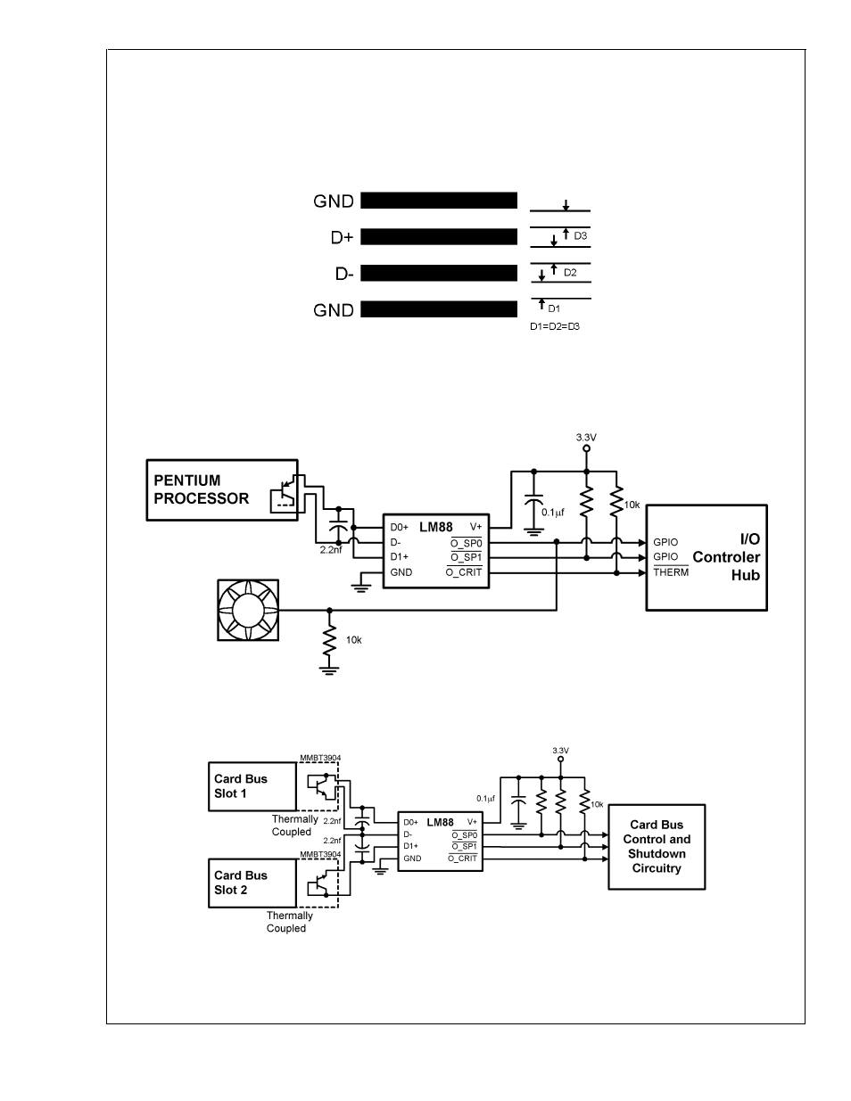
3.0 Applications Circuits
10132633
FIGURE 4. Ideal Diode Trace Layout
10132614
FIGURE 5. Pentium processor Thermal Management with Fan Control
10132603
FIGURE 6. Card Bus Thermal Management
LM88
www.national.com
8
See also other documents in the category Rainbow Electronics Sensors:
- MAX5151 (16 pages)
- MAXQ3108 (64 pages)
- MAX5661 (39 pages)
- MAX6691 (7 pages)
- MAX5362 (12 pages)
- ADC10158 (26 pages)
- MAX8922L (14 pages)
- MAX8596Z (8 pages)
- MAX7491 (18 pages)
- MAX15040 (15 pages)
- MAX5177 (16 pages)
- ADC08138 (22 pages)
- MAX5961 (42 pages)
- T89C51RD2 (86 pages)
- MAX16055 (9 pages)
- MAX6659 (17 pages)
- ADC0820 (20 pages)
- MAX6678 (19 pages)
- MAX8884Z (15 pages)
- MAX16915 (9 pages)
- MAX8620 (18 pages)
- MAX5144 (12 pages)
- MAX6670 (8 pages)
- MAX8760 (39 pages)
- W78C32C (14 pages)
- MX7533 (8 pages)
- MAX8727 (13 pages)
- MAX9053 (15 pages)
- W78C54 (16 pages)
- MAX8614B (15 pages)
- W90N740 (219 pages)
- MAX6626 (13 pages)
- ADC10738 (30 pages)
- MAX17000 (31 pages)
- MAX5051 (21 pages)
- MAXQ1004 (18 pages)
- MAX6871 (51 pages)
- MX7847 (12 pages)
- MAX6608 (6 pages)
- MAX17083 (15 pages)
- MAX6641 (17 pages)
- MAX5251 (16 pages)
- MAX6338 (8 pages)
- MAX6690 (16 pages)
- MAX8668 (18 pages)