Multichannel remote/local temperature sensors – Rainbow Electronics MAX1989 User Manual
Page 2
MAX1668/MAX1805/MAX1989
†
Multichannel Remote/Local
Temperature Sensors
2
_______________________________________________________________________________________
ABSOLUTE MAXIMUM RATINGS
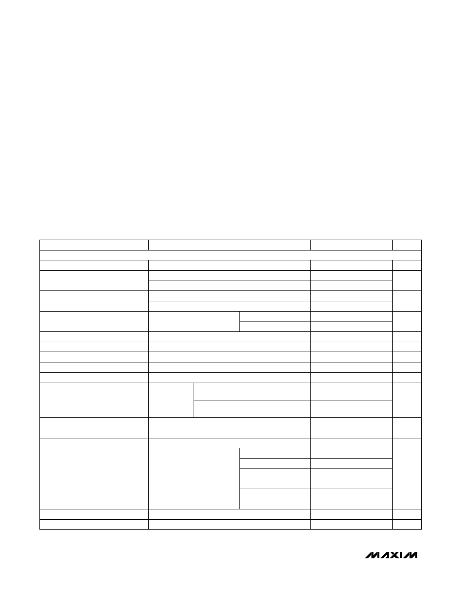
ELECTRICAL CHARACTERISTICS
(V
CC
= +3.3V, STBY = V
CC
, configuration byte = X0XXXX00, T
A
= 0°C to +125°C, unless otherwise noted.)
Stresses beyond those listed under “Absolute Maximum Ratings” may cause permanent damage to the device. These are stress ratings only, and functional
operation of the device at these or any other conditions beyond those indicated in the operational sections of the specifications is not implied. Exposure to
absolute maximum rating conditions for extended periods may affect device reliability.
V
CC
to GND ..............................................................-0.3V to +6V
DXP_, ADD_, STBY to GND........................-0.3V to (V
CC
+ 0.3V)
DXN_ to GND ........................................................-0.3V to +0.8V
SMBCLK, SMBDATA, ALERT to GND ......................-0.3V to +6V
SMBDATA, ALERT Current .................................-1mA to +50mA
DXN_ Current......................................................................±1mA
Continuous Power Dissipation (T
A
= +70°C)
QSOP (derate 8.30mW/°C above +70°C) ....................667mW
Operating Temperature Range .........................-55°C to +125°C
Junction Temperature ......................................................+150°C
Storage Temperature Range .............................-65°C to +150°C
Lead Temperature (soldering, 10s) .................................+300°C
DXP_ forced to 1.5V
Remote-Diode Source Current
Low level (POR state)
Configuration byte =
X0XXXX10, high level
Configuration byte =
X0XXXX01, high level
High level (POR state)
7
10
13
200
50
DXN_ Source Voltage
0.7
V
Hardware or software standby,
SMBCLK at 10kHz
SMBus static
T
A
= 0°C to +85°C
T
A
= +60°C to +100°C
Average measured over 4s; logic inputs forced
V
CC
or GND
Temperature Error, Local Diode
(Notes 1, 2)
-3.5
+3.5
°C
-2.5
+2.5
Including long-term drift
Temperature Error, Remote Diode
(Notes 2, 3)
-5
+5
°C
-3
+3
T
R
= -55°C to +125°C
T
R
= +60°C to +100°C
PARAMETER
MIN
TYP
MAX
UNITS
Undervoltage Lockout Hysteresis
50
mV
Undervoltage Lockout Threshold
2.60
2.8
2.95
V
Supply Voltage Range
3.0
5.5
V
Initial Temperature Error,
Local Diode (Note 2)
-3
+3
°C
Power-On Reset (POR) Threshold
1.3
1.8
2.3
V
POR Threshold Hysteresis
50
mV
3
10
Standby Supply Current
5
12
µA
Temperature Resolution (Note 1)
8
Bits
-2
+2
Average Operating Supply Current
400
700
µA
Conversion Time
260
320
380
ms
70
100
130
µA
Address Pin Bias Current
160
µA
CONDITIONS
V
CC
input, disables A/D conversion, rising edge
T
A
= 0°C to +125°C
V
CC
, falling edge
From stop bit to conversion complete (all channels)
Logic inputs
forced to V
CC
or GND
ADD0, ADD1; momentary upon power-on reset
Monotonicity guaranteed
T
A
= +60°C to +100°C
ADC AND POWER SUPPLY