Electrical characteristics (continued) – Rainbow Electronics MAX742 User Manual
Page 3
MAX742
Switch-Mode Regulator with
+5V to ±12V or ±15V Dual Output
_______________________________________________________________________________________
3
Note 1:
Devices are 100% tested to these limits under 0mA to 100mA and to 125mA conditions using automatic test equipment.
The ability to drive loads up to 1A is guaranteed by the current-limit threshold, output swing, and the output current
source/sink tests. See Figures 2 and 3.
Note 2:
Actual load capability of the circuit of Figure 2 is ±200mA in ±15V mode and ±250mA in ±12V mode. Load regulation is
tested at lower limits due to test equipment limitations.
Note 3:
Guaranteed by design.
Note 4:
Measured at Point A, circuit of Figure 2, with PDRV disconnected.
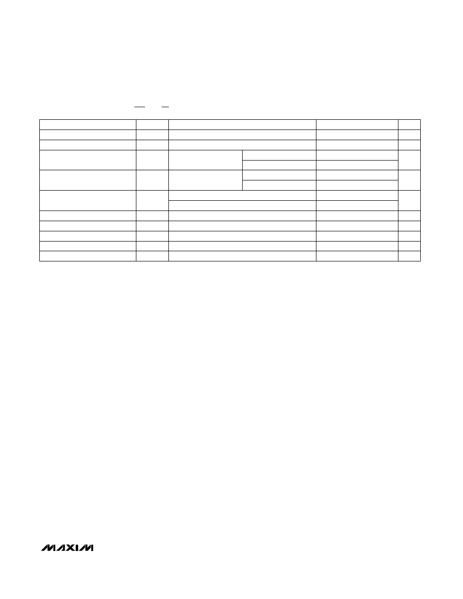
ELECTRICAL CHARACTERISTICS (continued)
(Circuit of Figure 2, V+ = 5V, 100/200 = 12/15 = 0V; T
A
= T
MIN
to T
MAX
, unless otherwise noted.)
EXT+, EXT-, I
L
= -1mA, V+ = 4.5V, PDRV= -3V
EXT+, EXT-, I
L
= 1mA, V+ = 4.5V, PDRV= -3V
V+ = 3.8V, SS = 2V
CC+, CC-
V+ = 4.5V, PDRV = -3V,
T
A
= +25°C
V+ = 4.5V, I
L
= -5mA, T
A
= +25°C
SS = 0V
CONDITIONS
mA
-2
-0.5
Soft-Start Sink Current
µA
3
7
Soft-Start Source Current
V
-2.8
V
OL
V
4.3
V
OH
Output Voltage High
Output Voltage Low
°C
190
Thermal-Shutdown Threshold
k
Ω
10
Compensation Pin Impedance
mA
100
200
Output Sink Current
200
350
V
-3
PUMP Output Voltage (Note 4)
UNITS
MIN
TYP
MAX
SYMBOL
PARAMETER
EXT+ = 4.5V
EXT- = 4.5V
EXT+ = 0V
V+ = 4.5V, PDRV = -3V,
T
A
= +25°C
EXT- = -3V
mA
-200
-100
Output Source Current
-350
-200
EXT+, C
LOAD
= 2nF
ns
70
Output Rise/Fall Time
100
EXT-, C
LOAD
= 4nF, PDRV = -3V