Chip information – Rainbow Electronics MAX758A User Manual
Page 9
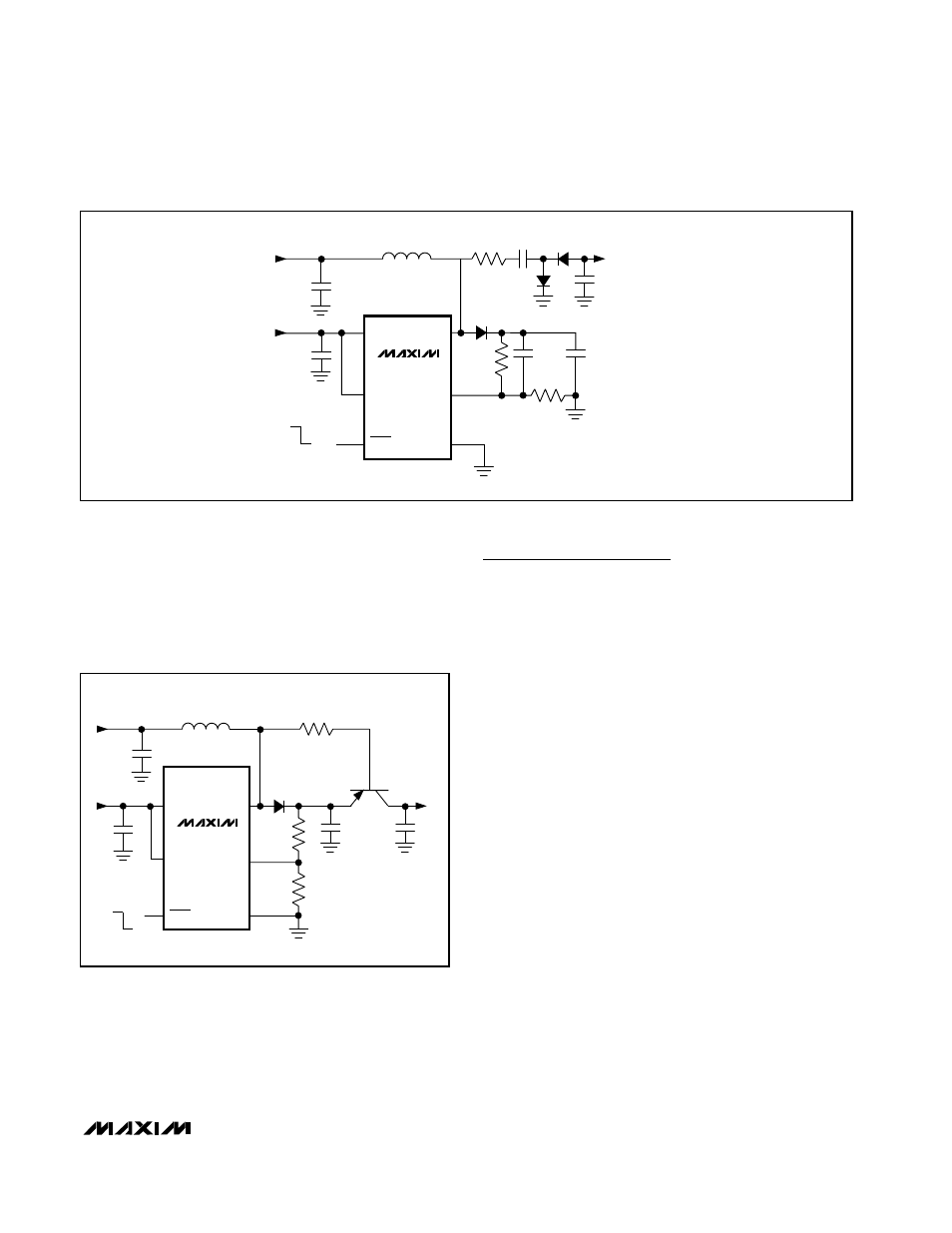
saturation region. When shut down, the input voltage
exceeds the emitter voltage so the inactive transistor
provides high-impedance isolation between the input
and output. Efficiency will be slightly degraded due to
the PNP transistor saturation voltage and base current.
V
IN
=
0.8V TO
V
OUT
V
NEG
-19V
V
CC
=
2.4V TO
5.5V
D3**
D2*
D1*
R1
240k
R2
16.5k
ON
OFF
SHDN
V
CC
LIM
GND
LX
FB
MAX1605
L1
10
µH
C3
0.1
µF
C6
0.1
µF
C4
0.01
µF
C1
1000pF
C2
1
µF
R3
1
Ω
C5
1
µF
*D1, D2 = CENTRAL SEMICONDUCTOR
CMPD7000 DUAL
**D3 = CENTRAL SEMICONDUCTOR
CMSD4448 (1N4148)
Figure 4. Negative Voltage for LCD Bias
MAX1605
28V Internal Switch LCD Bias Supply
in SOT23
_______________________________________________________________________________________
9
V
IN
= 0.8V TO V
OUT
R3 = 180k
V
CC
= 2.4V TO 5.5V
V
OUT
= 18V
ON
OFF
R1
R2
SHDN
V
CC
2N2907A
V
SET
= 18.3V
(V
OUT
+0.3V)
LIM
GND
LX
FB
MAX1605
L1
10
µH
Figure 5. Output Disconnected in Shutdown
Chip Information
TRANSISTOR COUNT: 2329
- MAX5151 (16 pages)
- MAXQ3108 (64 pages)
- MAX5661 (39 pages)
- MAX6691 (7 pages)
- MAX5362 (12 pages)
- ADC10158 (26 pages)
- MAX8922L (14 pages)
- MAX8596Z (8 pages)
- MAX7491 (18 pages)
- MAX15040 (15 pages)
- MAX5177 (16 pages)
- ADC08138 (22 pages)
- MAX5961 (42 pages)
- T89C51RD2 (86 pages)
- MAX16055 (9 pages)
- MAX6659 (17 pages)
- ADC0820 (20 pages)
- MAX6678 (19 pages)
- MAX8884Z (15 pages)
- MAX16915 (9 pages)
- MAX8620 (18 pages)
- MAX5144 (12 pages)
- MAX6670 (8 pages)
- MAX8760 (39 pages)
- W78C32C (14 pages)
- MX7533 (8 pages)
- MAX8727 (13 pages)
- MAX9053 (15 pages)
- W78C54 (16 pages)
- MAX8614B (15 pages)
- W90N740 (219 pages)
- MAX6626 (13 pages)
- ADC10738 (30 pages)
- MAX17000 (31 pages)
- MAX5051 (21 pages)
- MAXQ1004 (18 pages)
- MAX6871 (51 pages)
- MX7847 (12 pages)
- MAX6608 (6 pages)
- MAX17083 (15 pages)
- MAX6641 (17 pages)
- MAX5251 (16 pages)
- MAX6338 (8 pages)
- MAX6690 (16 pages)
- MAX8668 (18 pages)