Pin description, Detailed description, Control scheme – Rainbow Electronics MAX758A User Manual
Page 6
MAX1605
28V Internal Switch LCD Bias Supply
in SOT23
6
_______________________________________________________________________________________
Pin Description
PIN
NAME
FUNCTION
1
SHDN
Active-Low Shutdown Input. A logic low shuts down the device and reduces the supply current
to 0.1
µA. Connect SHDN to V
CC
for normal operation.
2
V
CC
IC Supply Voltage (+2.4V to +5.5V). Bypass V
CC
to GND with a 0.1
µF or greater capacitor.
3
GND
Ground
4
LX
Inductor Connection. The drain of an internal 28V N-channel MOSFET. LX is high impedance in
shutdown.
5
LIM
Inductor Current Limit Selection. Connect LIM to V
CC
for 500mA, leave LIM floating for 250mA,
or connect LIM to GND for 125mA.
6
FB
Feedback Input. Connect to a resistive-divider network between the output (V
OUT
) and FB to set
the output voltage between V
IN
and 28V. The feedback threshold is 1.25V.
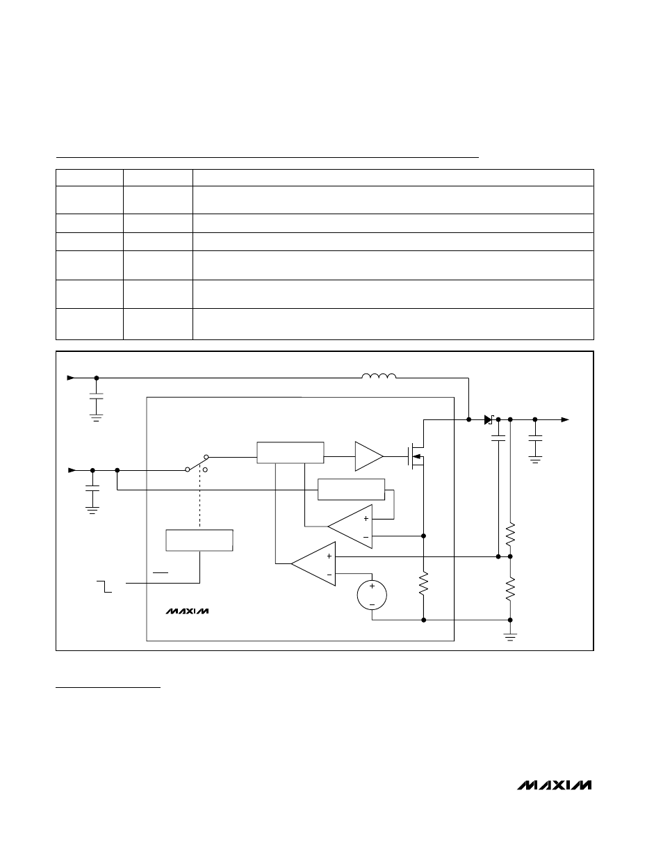
Detailed Description
The MAX1605 compact, step-up DC-DC converter
operates from a +2.4V to +5.5V supply. Consuming
only 18µA of supply current, the device includes an
internal switching MOSFET with 1
Ω on-resistance and
selectable current limit (Figure 1). During startup, the
MAX1605 extends the minimum off-time, limiting initial
surge current. The MAX1605 also features a shutdown
mode.
Control Scheme
The MAX1605 features a minimum off-time, current-lim-
ited control scheme. The duty cycle is governed by a
pair of one-shots that set a minimum off-time and a
maximum on-time. The switching frequency can be up
SHDN
ON
OFF
V
CC
= 2.4V TO 5.5V
V
OUT
= V
IN
TO 28V
CONTROL
LOGIC
ERROR
AMPLIFIER
1.25V
GND
FB
R2
V
CC
LX
N
C
OUT
L1
10
µH
R1
LIM
V
IN
= 0.8V TO V
OUT
C
FF
SHUTDOWN
LOGIC
CURRENT
LIMIT
MAX1605
Figure 1. Functional Diagram