Low-noise step-up dc-dc converter, Max1790 – Rainbow Electronics MAX1790 User Manual
Page 8
External component value choice is primarily dictated
by the output voltage and the maximum load current,
as well as maximum and minimum input voltages.
Begin by selecting an inductor value. Once L is known,
choose the diode and capacitors.
Inductor Selection
Inductor selection depends on input voltage, output
voltage, maximum current, switching frequency, size,
and availability of inductor values. Other factors can
include efficiency and ripple voltage. Inductors are
specified by their inductance (L), peak current (I
PK
),
and resistance (L
r
). The following boost-circuit equa-
tions are useful in choosing the inductor values based
on the application. They allow the trading of peak cur-
rent and inductor value while allowing for consideration
of component availability and cost.
The equation used here includes a constant LIR, which
is the ratio of the inductor peak-peak AC current to
maximum average DC inductor current. A good com-
promise between size of the inductor and loss and out-
put ripple is to choose an LIR of 0.3 to 0.5. The peak
inductor current is then given by:
The inductance value is then given by:
Considering the typical application circuit, the maxi-
mum DC load current (I
OUT(MAX)
) is 500mA with a 5V
output. The inductance value is then chosen to be
5.4µH, based on the above equations and using 85%
efficiency and a 640kHz operating frequency. The
inductor saturation current rating should be greater
than I
PK
. The resistance of the inductor windings
should be less than 0.5
Ω. To minimize radiated noise in
sensitive applications, use a shielded inductor.
Diode Selection
The output diode should be rated to handle the output
voltage and the peak switch current. Make sure that the
diode’s peak current rating is at least I
PK
and that its
L
V
V
V
V
LIR I
f
IN(MIN)
2
OUT
IN(MIN)
OUT
2
OUT(MAX)
OSC
=
(
)
−
(
)
⋅ ⋅
⋅
⋅
⋅
η
I
I
V
V
1
LIR
2
PK
OUT(MAX)
OUT
IN(MIN)
=
(
)
+
⋅
⋅
⋅
η
Low-Noise Step-Up DC-DC Converter
8
_______________________________________________________________________________________
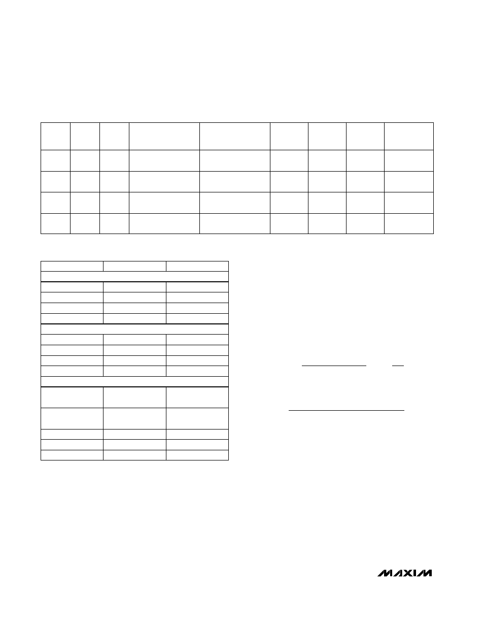
Table 1. Component Selection
Table 2. Component Suppliers
847-639-6400
561-241-7876
847-956-0666
PHONE
847-639-1469
Coilcraft
561-241-9339
Coiltronics
847-956-0702
Sumida USA
FAX
SUPPLIER
803-946-0690
408-986-0424
619-661-6835
847-297-0070
803-626-3123
AVX
408-986-1442
Kemet
619-661-1055
Sanyo
847-699-1194
Toko
516-435-1110
310-322-3331
516-543-7100
602-303-5454
408-573-4150
847-843-7500
516-864-7630
Zetex
847-843-2798
Nihon
516-435-1824
Central
Semiconductor
310-322-3332
International
Rectifier
602-994-6430
Motorola
408-573-4159
Taiyo Yuden
MAX1790
V
IN
(V)
f
OSC
(Hz)
R
COMP
(k
Ω)
C
COMP2
(pF)
3.3
1.2M
91
33
3.3
640k
62
56
3.3
3.3
640k
120
33
1.2M
180
20
TYPICAL
I
OUT(MAX)
(mA)
800
800
250
250
C
COMP
(pF)
C
OUT
(µF)
390
820
47 tantalum
(6TPA47M)
47 tantalum
(6TPA47M)
1200
650
L
(µH)
2.7 (Sumida
CDRH4018-2R7)
5.4 (Sumida
CDRH5D18-5R4NC)
10 (Sumida
CDRH5D18-100NC)
5.4 (Sumida
CDRH5D18-5R4NC)
V
OUT
(V)
33 tantalum (AVX
TPSD336020R0200)
5
33 tantalum (AVX
TPSD336020R0200)
5
12
12
Inductors
Capacitors
Diodes