Max1122, Static parameter definitions, Dynamic parameter definitions – Rainbow Electronics MAX1122 User Manual
Page 16
MAX1122
Static Parameter Definitions
Integral Nonlinearity (INL)
Integral nonlinearity is the deviation of the values on an
actual transfer function from a straight line. This straight
line can be either a best straight-line fit or a line drawn
between the end points of the transfer function, once
offset and gain errors have been nullified. However, the
static linearity parameters for the MAX1122 are mea-
sured using the histogram method with an input fre-
quency of 10MHz.
Differential Nonlinearly (DNL)
Differential nonlinearity is the difference between an
actual step width and the ideal value of 1 LSB. A DNL
error specification of less than 1 LSB guarantees no
missing codes and a monotonic transfer function. The
MAX1122’s DNL specification is measured with the his-
togram method based on a 10MHz input tone.
Dynamic Parameter Definitions
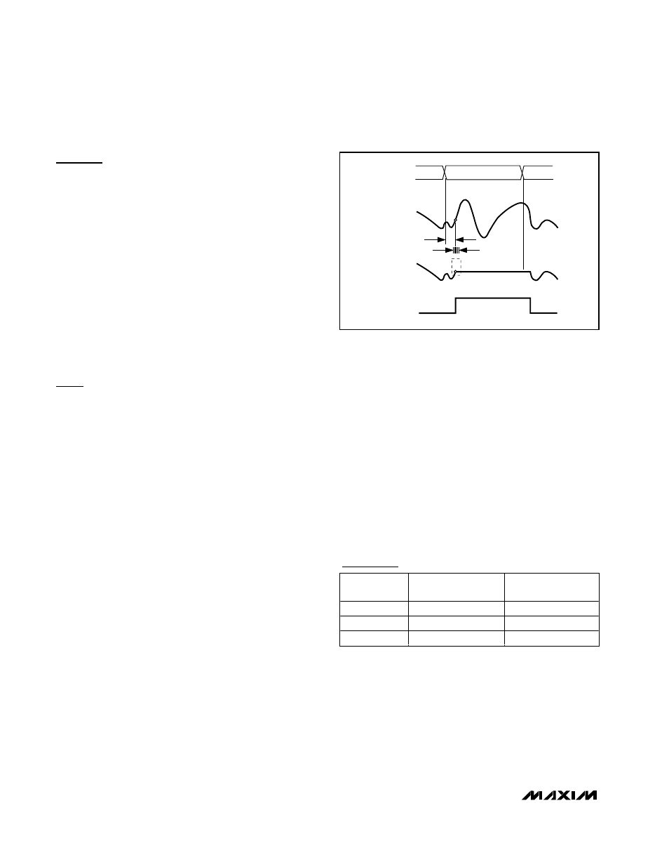
Aperture Jitter
Figure 11 depicts the aperture jitter (t
AJ
), which is the
sample-to-sample variation in the aperture delay.
Aperture Delay
Aperture delay (t
AD
) is the time defined between the
falling edge of the sampling clock and the instant when
an actual sample is taken (Figure 11).
Signal-to-Noise Ratio (SNR)
For a waveform perfectly reconstructed from digital
samples, the theoretical maximum SNR is the ratio of
the full-scale analog input (RMS value) to the RMS
quantization error (residual error). The ideal, theoretical
minimum analog-to-digital noise is caused by quantiza-
tion error only and results directly from the ADC’s reso-
lution (N bits):
SNR
dB[max]
= 6.02
dB
x N + 1.76
dB
In reality, other noise sources such as thermal noise,
clock jitter, signal phase noise, and transfer function
nonlinearities are also contributing to the SNR calcula-
tion and should be considered when determining the
SNR in ADC.
Signal-to-Noise Plus Distortion (SINAD)
SINAD is computed by taking the ratio of the RMS sig-
nal to all spectral components excluding the fundamen-
tal and the DC offset. In case of the MAX1122, SINAD is
computed from a curve fit.
Spurious-Free Dynamic Range (SFDR)
SFDR is the ratio of RMS amplitude of the carrier fre-
quency (maximum signal component) to the RMS value
of the next-largest noise or harmonic distortion compo-
nent. SFDR is usually measured in dBc with respect to
the carrier frequency amplitude or in dBFS with respect
to the ADC’s full-scale range.
Two-Tone Intermodulation Distortion (IMD)
The two-tone IMD is the ratio expressed in decibels of
either input tone to the worst 3rd-order (or higher) inter-
modulation products. The individual input tone levels
are at -7dB full scale.
1.8V, 10-Bit, 170Msps Analog-to-Digital Converter
with LVDS Outputs for Wideband Applications
16
______________________________________________________________________________________
HOLD
ANALOG
INPUT
SAMPLED
DATA (T/H)
T/H
t
AD
t
AJ
TRACK
TRACK
CLKN
CLKP
Figure 11. Aperture Jitter/Delay Specifications
PART
RESOLUTION
(Bits)
SPEED GRADE
(Msps)
MAX1123
10
210
MAX1124
10
250
MAX1121
8
250
Pin-Compatible Higher Speed/
Lower Resolution Versions