Dynamic parameter definitions, Pin configuration, Differential nonlinearly (dnl) – Rainbow Electronics MAX1419 User Manual
Page 16: Aperture delay, Aperture jitter, Signal-to-noise ratio (snr), Signal-to-noise plus distortion (sinad), Single-tone spurious-free dynamic range (sfdr), Two-tone spurious-free dynamic range (sfdr, Two-tone intermodulation distortion (imd)
MAX1419
15-Bit, 65Msps ADC with -79.3dBFS
Noise Floor for Baseband Applications
16
______________________________________________________________________________________
Differential Nonlinearly (DNL)
Differential nonlinearity is the difference between an
actual step width and the ideal value of 1 LSB. A DNL
error specification of less than 1 LSB guarantees no
missing codes and a monotonic transfer function. The
MAX1419’s DNL specification is measured with the his-
togram method based on a 15MHz input tone.
Dynamic Parameter Definitions
Aperture Delay
Aperture delay (t
AD
) is the time defined between the
rising edge of the sampling clock and the instant when
an actual sample is taken (Figure 4).
Aperture Jitter
The aperture jitter (t
AJ
) is the sample-to-sample varia-
tion in the aperture delay.
Signal-to-Noise Ratio (SNR)
For a waveform perfectly reconstructed from digital
samples, the theoretical maximum SNR is the ratio of
the full-scale analog input (RMS value) to the RMS
quantization error (residual error). The ideal, theoretical
minimum analog-to-digital noise is caused by quantiza-
tion error only and results directly from the ADC’s reso-
lution (N bits):
SNR
dB[max]
= 6.02
dB
x N + 1.76
dB
In reality, other noise sources such as thermal noise,
clock jitter, signal phase noise, and transfer function
nonlinearities are also contributing to the SNR calcula-
tion and should be considered when determining the
SNR in ADC. For a near-full-scale analog input signal
(-0.5dBFS to -1dBFS), thermal and quantization noise
are uniformly distributed across the frequency bins.
Error energy caused by transfer function nonlinearities
on the other hand is not distributed uniformly, but con-
fined to the first few hundred odd-order harmonics.
BTS applications, which are the main target application
for the MAX1419 usually do not care about excess
noise and error energy in close proximity to the carrier
frequency or to DC. These low-frequency and sideband
errors are test system artifacts and are of no conse-
quence to the BTS channel sensitivity. They are there-
fore excluded from the SNR calculation.
Signal-to-Noise Plus Distortion (SINAD)
SINAD is computed by taking the ratio of the RMS sig-
nal to all spectral components excluding the fundamen-
tal and the DC offset.
Single-Tone Spurious-Free
Dynamic Range (SFDR)
SFDR is the ratio of RMS amplitude of the carrier fre-
quency (maximum signal component) to the RMS value
of the next-largest noise or harmonic distortion compo-
nent. SFDR is usually measured in dBc with respect to
the carrier frequency amplitude or in dBFS with respect
to the ADC’s full-scale range.
Two-Tone Spurious-Free
Dynamic Range (SFDR
TT
)
SFDR
TT
represents the ratio of the RMS value of either
input tone to the RMS value of the peak spurious com-
ponent in the power spectrum. This peak spur can be
an intermodulation product of the two input test tones.
Two-Tone Intermodulation Distortion (IMD)
The two-tone IMD is the ratio expressed in decibels of
either input tone to the worst 3rd-order (or higher) inter-
modulation products. The individual input tone levels
are at -7dB full scale.
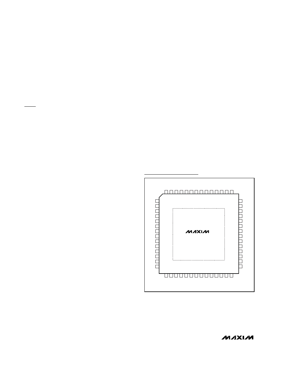
GND
1
GND
2
GND
3
CLKP
4
CLKN
5
GND
6
AV
CC
7
AV
CC
8
GND
9
INP 10
INN 11
GND 12
CM 13
GND 14
DRV
CC
42
DRV
CC
41
D7
40
D6
39
D5
38
D4
37
D3
36
D2
35
D1
34
D0
33
DOR
32
DRV
CC
31
GND
30
DV
CC
29
GND
15
GND
16
GND
17
18
19
GND
20
AV
CC
21
AV
CC
AV
CC
AV
CC
AV
CC
AV
CC
AV
CC
22
GND
23
24
25
GND
GND
26
27
28
GND
56
GND
55
GND
54
53
52
DRV
CC
51
GND
50
GND
DA
V
D14
D12
D11
D8
49
D13
48
47
46
D9
D10
45
44
43
MAX1419
TOP VIEW
THIN QFN
EP
Pin Configuration