Rainbow Electronics MAX754 User Manual
Page 10
MAX753/MAX754
CCFL Backlight and
LCD Contrast Controllers
10
______________________________________________________________________________________
PARAMETER
SYMBOL
MIN
TYP
MAX
UNITS
Strike Voltage (V
S
)
V
S,RMS
1100
1500
V
RMS
Discharging Tube Current (I
L
)
I
LAMP,RMS
0.001376
0.005
A
RMS
Discharging Tube Voltage (V
L
)
V
LAMP,RMS
435
V
RMS
Bias Voltage
V
LCD
16.3
32.6
V
Output Current
I
LCD
0.0245
A
T1 Turns Ratio (Sec/Pri) (Note 2)
n
171
T1 Resonating Inductance (Note 2)
L
MAG
0.000045
H
C9 Value (Note 3)
C
RES
2.2E-07
F
C10 Value
C
BAL
1.5E-11
F
Royer Frequency
w
317820.86
rad/s
Reference Voltage
V
REF
1.25
V
Second Volts Constant
sV
0.000008
2.4E-05
sV
R8 Current-Sensing Resistor
R8
555.36037
Ω
Secondary Voltage Phase vs. Tube Voltage
phi
-1.1776341
Radian
Secondary Limit Voltage
V
LIM
1350
V
RMS
T1 Center-Tap Limit Peak Voltage
11.164844
V
PEAK
R5/R6
R
OTP,RATIO
0.1341944
Ω
/
Ω
V
IN(min)
Full-Load Switching Period
T
FL
1.639E-06
s
L2 Inductance
L2
1.96E-05
2.4E-05
H
L2 Peak Currrent
1.22704
A
R4/R3
R
LCD,RATIO
0.0398724
Ω
/
Ω
Input Voltage
V
IN
5.978103
18
V
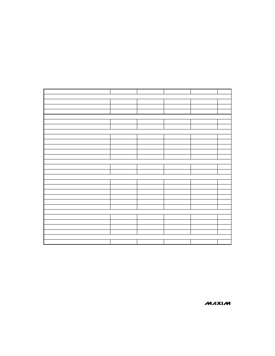
Table 2. CCFL Circuit Design Example (Note 1)
T1 Center-Tap Peak Voltage
V
TAP,PK
9.3903817
V
PEAK
Note 1:
To perform your own calculations for the parameters given in Table 2 (Design Example), use the equations given in Table
3 (Design Equations).
Note 2:
T1 = Sumida’s EPS207
Note 3:
C9 = Wima’s SMD 7.3 __/63
CCFL Specifications
LCD Contrast Voltage Specifications
Royer Specifications
MAX754 Specifications
CCFL Circuit Calculations
LCD Circuit Calculations
Application Circuit Operating Range