Pin plastic small-outline package – Rainbow Electronics MAX853 User Manual
Page 8
MAX850–MAX853
Low-Noise, Regulated, Negative
Charge-Pump Power Supplies for GaAsFET Bias
8
______________________________________________________________________________________
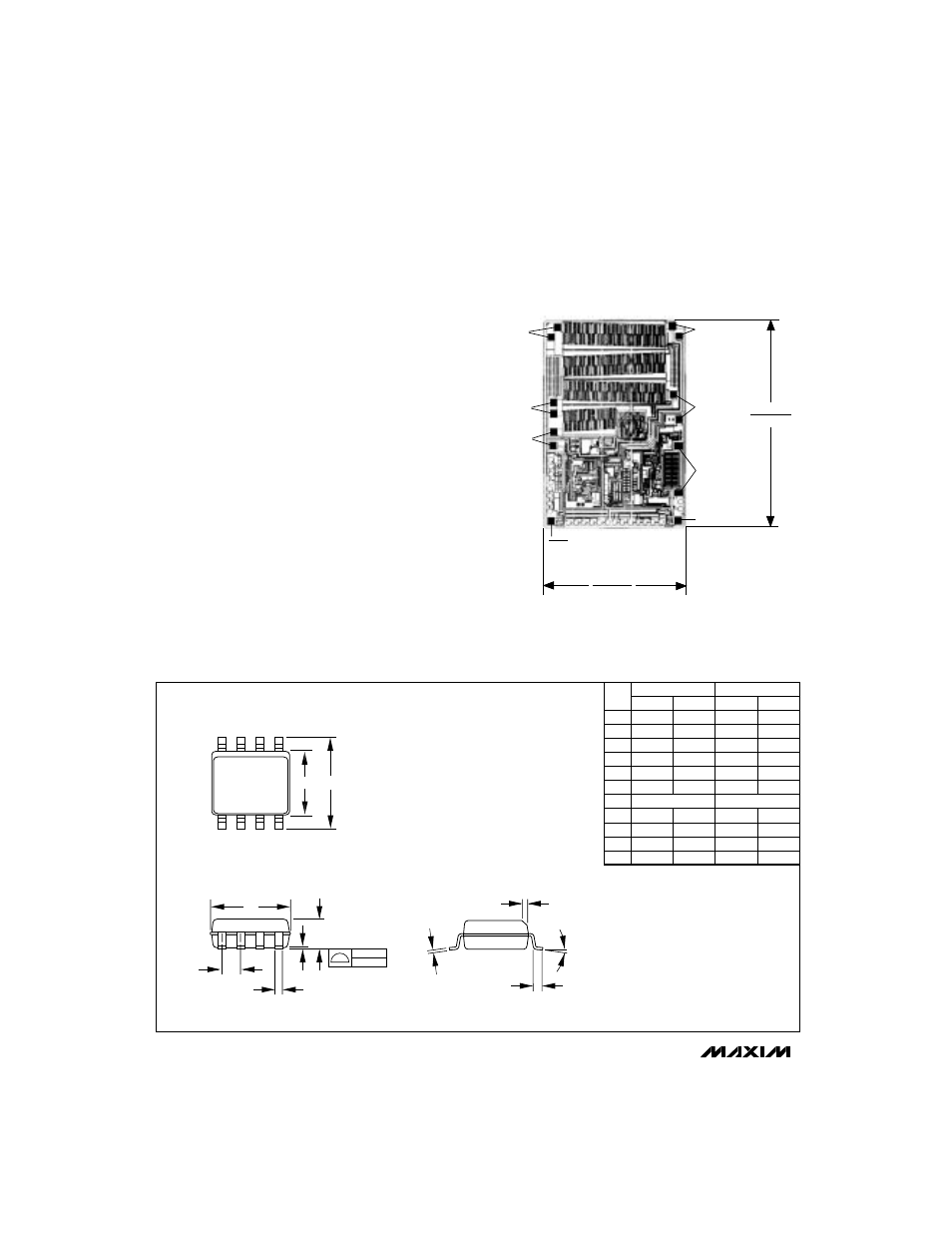
___________________Chip Topography
________________________________________________________Package Information
sensitivity and interference. The clock must be a square wave
between 40% and 60% duty cycle. The maximum clock fre-
quency is 250kHz, and the minimum frequency is 50kHz.
Layout and Grounding
Good layout is important, primarily for good noise perfor-
mance.
1) Mount all components as close together as possible.
2) Keep traces short to minimize parasitic inductance
and capacitance. This includes connections to FB.
3) Use a ground plane.
Noise and Ripple Measurement
Accurately measuring the output noise and ripple is a chal-
lenge. Brief differences in ground potential between the
MAX850–MAX853 circuit and the oscilloscope (which result
from the charge pump’s switching action) cause ground
currents in the probe’s wires, inducing sharp voltage spikes.
For best results, measure directly across the output capaci-
tor (C4). Do not use the ground lead of the oscilloscope
probe; instead, remove the probe’s tip cover and touch the
ground ring on the probe directly to C4’s ground terminal.
You can also use a Tektronix chassis mount test jack (part
no. 131-0258) to connect your scope probe directly. This
direct connection gives the most accurate noise and rip-
ple measurement.
FB (MAX850–852)
CONT (MAX853)
OUT
GND
IN
NEGOUT
C1-
C1+
SHDN (MAX850/853)
SHDN (MAX851)
OSC (MAX852)
0.127"
(3.226mm)
0.085"
(2.159mm)
TRANSISTOR COUNT: 164
SUBSTRATE CONNECTED TO IN
L
DIM
A
A1
B
C
D
E
e
H
h
L
α
MIN
0.053
0.004
0.014
0.007
0.189
0.150
0.228
0.010
0.016
0˚
MAX
0.069
0.010
0.019
0.010
0.197
0.157
0.244
0.020
0.050
8˚
MIN
1.35
0.10
0.35
0.19
4.80
3.80
5.80
0.25
0.40
0˚
MAX
1.75
0.25
0.49
0.25
5.00
4.00
6.20
0.50
1.27
8˚
INCHES
MILLIMETERS
α
8-PIN PLASTIC
SMALL-OUTLINE
PACKAGE
H
E
D
e
A
A1
C
h x 45˚
0.127mm
0.004in.
B
1.27 BSC
0.050 BSC
21-325A