Table 1. setup byte format – Rainbow Electronics MAX1139 User Manual
Page 13
Configuration/Setup Bytes (Write Cycle)
A write cycle begins with the bus master issuing a
START condition followed by seven address bits (Figure
7) and a write bit (R/W = 0). If the address byte is suc-
cessfully received, the MAX1136–MAX1139 (slave)
issues an acknowledge. The master then writes to the
slave. The slave recognizes the received byte as the
setup byte (Table 1) if the most significant bit (MSB) is
1. If the MSB is 0, the slave recognizes that byte as the
configuration byte (Table 3). The master can write either
one or two bytes to the slave in any order (setup byte
then configuration byte; configuration byte then setup
byte; setup byte or configuration byte only; Figure 9). If
the slave receives a byte successfully, it issues an
acknowledge. The master ends the write cycle by issu-
ing a STOP condition or a repeated START condition.
When operating in HS-mode, a STOP condition returns
the bus into F/S-mode (see the HS-Mode section).
MAX1136–MAX1139
2.7V to 3.6V and 4.5V to 5.5V, Low-Power,
4-/12-Channel, 2-Wire Serial 10-Bit ADCs
______________________________________________________________________________________
13
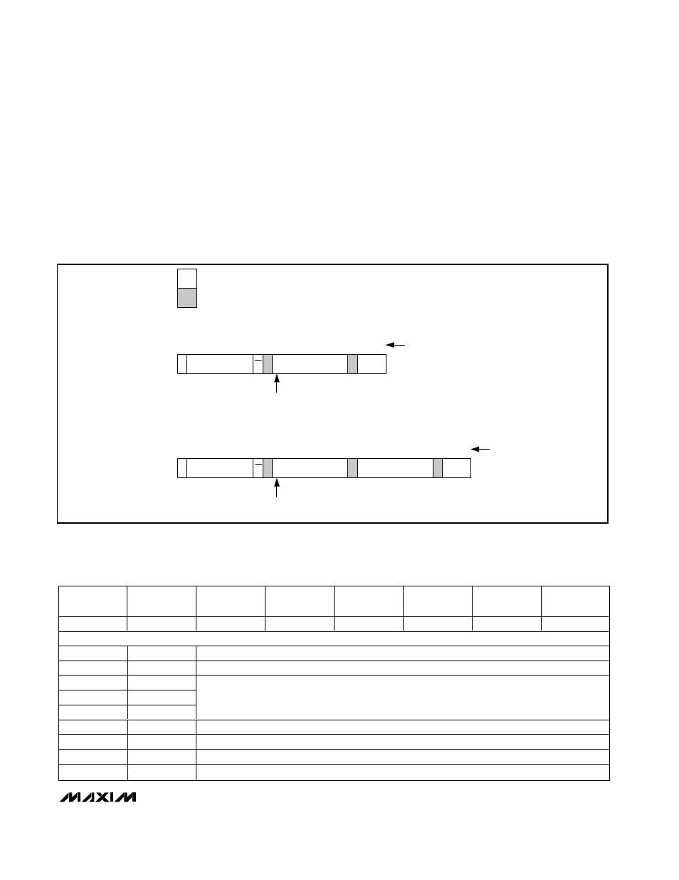
B. TWO-BYTE WRITE CYCLE
SLAVE TO MASTER
MASTER TO SLAVE
S
1
SLAVE ADDRESS
A
7
1 1
W
SETUP OR
CONFIGURATION BYTE
SETUP OR
CONFIGURATION BYTE
8
P or Sr
1
A
1
MSB DETERMINES WHETHER
SETUP OR CONFIGURATION BYTE
S
1
SLAVE ADDRESS
A
7
1 1
W
SETUP OR
CONFIGURATION BYTE
8
P or Sr
1
A
1
MSB DETERMINES WHETHER
SETUP OR CONFIGURATION BYTE
A
1
8
A. ONE- BYTE WRITE CYCLE
NUMBER OF BITS
NUMBER OF BITS
Figure 9. Write Cycle
BIT 7
(MSB)
BIT 6
BIT 5
BIT 4
BIT 3
BIT 2
BIT 1
BIT 0
(LSB)
REG
SEL2
SEL1
SEL0
CLK
BIP/UNI
RST
X
BIT
NAME
DESCRIPTION
7
REG
Register bit. 1 = setup byte, 0 = configuration byte (see Table 2).
6
SEL2
5
SEL1
4
SEL0
Three bits select the reference voltage and the state of AIN_/REF (Table 6). Defaulted to 000 at
power-up.
3
CLK
1 = external clock, 0 = internal clock. Defaulted to 0 at power-up.
2
BIP/UNI
1 = bipolar, 0 = unipolar. Defaulted to 0 at power-up.
1
RST
1 = no action, 0 = resets the configuration register to default. Setup register remains unchanged.
0
X
Don’t care, can be set to 1 or 0.
Table 1. Setup Byte Format