Pin description – Rainbow Electronics MAX1708 User Manual
Page 8
MAX1708
High-Frequency, High-Power, Low-Noise,
Step-Up DC-DC Converter
8
_______________________________________________________________________________________
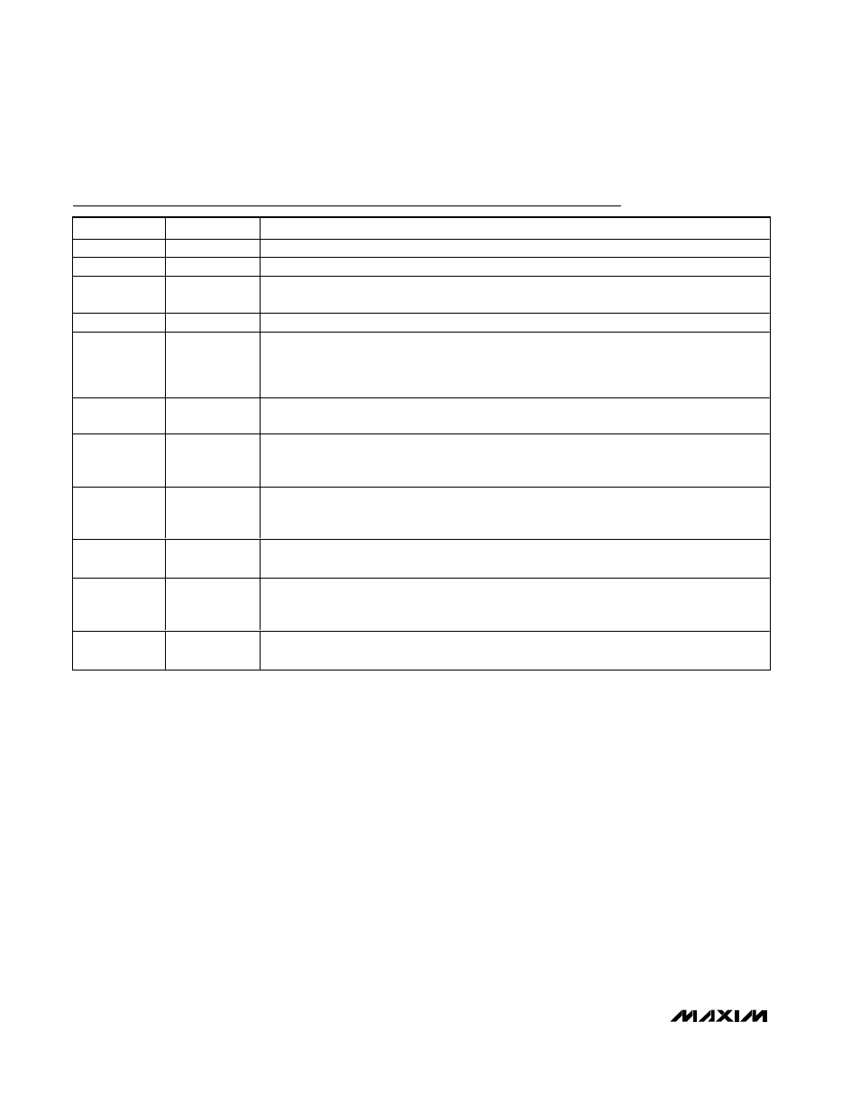
Pin Description
PIN
NAME
FUNCTION
1
ONB
Shutdown Input. When
ONB = high and ONA = low, the device turns off (Table 1).
2
ONA
On-Control Input. When ONA = high or
ONB = low, the device turns on (Table 1).
3, 4, 5
LX
Drain of N-Channel Power Switch. Connect pins 3, 4, and 5 together with wide traces. Connect
an external Schottky diode from LX to V
OUT
. (Figure 1)
6, 9
GND
Ground
7
SS/LIM
Soft-Start and/or Current-Limit Input. Connect a capacitor from SS/LIM to GND to control the
rate at which the device reaches current limit (soft-start). To reduce the current limit from the
preset values, connect a resistor from SS/LIM to GND (see Design Procedure). During
shutdown, SS/LIM is internally pulled to GND to discharge the soft-start capacitor.
8
REF
Voltage Reference Output. Bypass with a 0.22µF capacitor to GND. Maximum REF load is
50µA.
10
OUT
Output Voltage Sense Input. The device is powered from OUT. Bypass with a 0.1µF capacitor
to PGND with less than 5mm trace length. Connect a 2
Ω series resistor from the output filter
capacitor (0.1µF) to OUT (Figure 1).
11
FB
DC-DC Converter Feedback Input. Connect FB to GND for internally set output voltage (see
3.3/5 pin description). Connect a resistor-divider from the output to set the output voltage in the
+2.5V to +5.5V range. FB regulates to +1.24V (Figure 4).
12, 13, 14
PGND
Power Ground, Source of N-Channel Power MOSFET Switch. Connect pins 12, 13, and 14
together with wide traces.
15
3.3/5
Output Voltage Selection Input. When FB is connected to GND, the regulator uses internal
feedback to set the output voltage.
3.3/5 = low sets output to 3.3V; 3.3/5 = high sets output to
5V. If an external divider is used at FB, connect
3.3/5 to ground.
16
CLK
Clock Input for the DC-DC Converter. Connect to OUT for internal oscillator. Drive CLK with
an external clock for external synchronization.